S-5
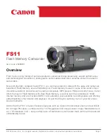
S3.3. LCD Schematic Diagram
29A.%&48
&A)0&
$75A5..%&
$75A5..%&
$75A5..%&
$75A5..%&
$75A5..%&
$75A5..%&
$75A5..%&
%.-A5..%&
$75A5..%&
$75A20.&
$75A20.&
$75A20.&
$75A20.&
$75A20.&
%.-A20.
$75A20.&
$75A20.&
$75A20.A*
$75A20.&
$75A20.A8
$.A%106
+%
%#$
%
(,,
%
8
%
8
8
%
%
%
%
(,,
%
=?
4
4
4
4
-
,,;%
.$
%*
%*
%*
.
)%-#
29A.48A&
29A.48A#
=?&+0
5%-
5%5
5&+
7%105'.
&+0
&+0
&+0
&+0
0%
0%
0%
0%
0%
0%
&+0
&+0
&+0
=?6'56
85;0%
*5;0%
8&&
8&&
855
855
855
&'
&176
&176
&176
&176
&176
&%.-
&176
#8&&
#855
8&&
4'5'6
%.-+0
=?0%
=?&176
=?&176
=?%.-5'.
=?6'56
=?2..A8%06
618+&'1
61/10+614
61219'4
HDC-HS300 Series
LCD Section
(Side R P.C.B.(2/2))
Schematic Diagram
10
9
8
7
6
5
4
3
2
1
G
F
E
D
C
B
A
Содержание HDC-HS300P
Страница 11: ...11 3 5 2 Precautions for installing HDD...
Страница 14: ...14 4 Specifications...
Страница 15: ...15...
Страница 16: ...16...
Страница 29: ...29 7 Disassembly and Assembly Instructions 7 1 Disassembly Flow Chart 7 2 PCB Location...
Страница 32: ...32 7 3 2 Removal of the Side Case R Unit Fig D2 Fig D3 7 3 3 Removal of the Side Case L Unit Fig D4...
Страница 33: ...33 7 3 4 Removal of the HDD Unit Fig D5 7 3 5 Removal of the Top Case Unit Fig D6...
Страница 35: ...35 Fig D11 7 3 8 Removal of the Lens Unit Fig D12 Fig D13 7 3 9 Removal of the Main P C B Fig D14...
Страница 36: ...36 7 3 10 Removal of the Sub P C B Fig D15 7 3 11 Removal of the Side R P C B and Cooling Fan Motor Fig D16...
Страница 38: ...38 Fig D20 7 3 15 Removal of the Monitor P C B Fig D21 Fig D22...
Страница 39: ...39 7 3 16 Removal of the LCD Fig D23 7 3 17 Removal of the Front P C B Fig D24...
Страница 40: ...40 7 3 18 Removal of the Camera Operation Unit Fig D25 7 3 19 Removal of the Barrier Motor Unit Fig D26...
Страница 41: ...41 Fig D27 7 3 20 Removal of the Barrier Unit and MF Ring Ornament Fig D28...
Страница 42: ...42 7 3 21 Removal of the Flash Unit Fig D29 7 3 22 Removal of the ECM Fig D30 Fig D31...
Страница 44: ...44 7 3 26 Removal of the Speaker Fig D35 7 3 27 Removal of the Shoe Angle and Grip Ornament Fig D36...
Страница 45: ...45 Fig D37 7 3 28 Removal of the MOS Unit and Optical Filter Fig D38 7 3 29 Removal of the Zoom Motor Fig D39...
Страница 84: ...S 33 S4 12 EVF FPC P C B 6 0 0 5 6 Foil Side HDC HS300 Series EVF FPC P C B 10 9 8 7 6 5 4 3 2 1 G F E D C B A...
Страница 88: ...S 37 S4 15 Front FPC P C B 6 6 HDC HS300 Series Front FPC P C B 10 9 8 7 6 5 4 3 2 1 G F E D C B A Foil Side...
Страница 89: ...S 38...
Страница 102: ...S6 3 EVF Section S 51 B45 55 B44 52 56 57 58 59 53 54 43 44 47 46 48 49 50 51 45 60 62 61 B46...
Страница 103: ...S6 4 LCD Section S 52 161 162 163 157 158 B151 B152 151 159 156 155 145 160 164 153 B153 B154 152 154...