What to Check If a Problem Occurs
FP2 Multi - wire Link Unit
A - 7
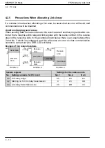
A.4 What to Do If a Transmission Error Occurs
Procedure 3
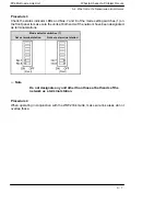
Check the status indicator LEDs and Nos. 7 and 8 of the mode setting switches (1) on
the front panel to make sure the units at both ends of the network have been designated
as terminal stations.
Mode selector switches (1)
Set as terminal station
Not set as terminal station
(Front)
(Front)
.
Note
Do not designate any unit other than those at both ends of the
network as a terminal station.
Procedure 4
When operating in conjunction with the W/W2 link mode, make sure link areas do not
overlap those.
Содержание FP2 Series
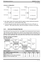
Страница 1: ...PROGRAMMABLE CONTROLLER FP2 Multi wire Link Unit Technical Manual ARCT1F302E 2 2008 11...
Страница 3: ......
Страница 8: ......
Страница 10: ...General Specifications FP2 Multi wire Link Unit 1 2...
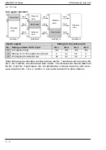
Страница 26: ...General Specifications FP2 Multi wire Link Unit 1 18 1 4 Confirming the Design Contents...
Страница 28: ...Parts and Its Functions FP2 Multi wire Link Unit 2 2...
Страница 36: ...Parts and Its Functions FP2 Multi wire Link Unit 2 10 2 2 Switch Settings...
Страница 37: ...Chapter 3 Wiring 3 1 Wiring 3 3 3 1 1 Transmission Cable Wiring 3 3 3 1 2 Crimp Terminal Specifications 3 4...
Страница 38: ...Wiring FP2 Multi wire Link Unit 3 2...
Страница 42: ...MEWNET W Mode FP2 Multi wire Link Unit 4 2...
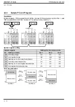
Страница 52: ...MEWNET W Mode FP2 Multi wire Link Unit 4 12 4 2 PC Link...
Страница 54: ...What to Check If a Problem Occurs FP2 Multi wire Link Unit A 2...
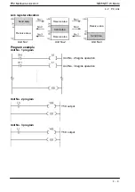
Страница 60: ...What to Check If a Problem Occurs FP2 Multi wire Link Unit A 8 A 4 What to Do If a Transmission Error Occurs...
Страница 61: ...Appendix B Dimensions...
Страница 62: ...Dimensions FP2 Multi wire Link Unit B 2...
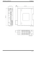
Страница 63: ...Dimensions FP2 Multi wire Link Unit B 3 unit mm in 28 1 102 100 3 937 12 6 0 496 93 3 661...
Страница 64: ...Dimensions FP2 Multi wire Link Unit B 4...
Страница 67: ......
Страница 68: ...ARCT1F302E 2 200811 ACG M302E 2...

