Wiring
FP2 Multi-wire Link Unit
3 - 4
3.1
Wiring
3.1.2
Crimp Terminal Specifications
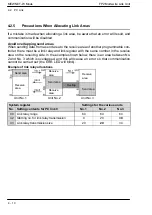
M3 terminal screws are used for the terminals on the FP2 Multi - wire link unit. Crimp ter-
minals with the shape shown below should be used.
Fasten the terminals securely applying a tightening torque of 0.5 to 0.6 N
S
m.
6 mm/0.236 in. or less
3.2 mm/0.126 in. or more
Содержание FP2 Series
Страница 1: ...PROGRAMMABLE CONTROLLER FP2 Multi wire Link Unit Technical Manual ARCT1F302E 2 2008 11...
Страница 3: ......
Страница 8: ......
Страница 10: ...General Specifications FP2 Multi wire Link Unit 1 2...
Страница 26: ...General Specifications FP2 Multi wire Link Unit 1 18 1 4 Confirming the Design Contents...
Страница 28: ...Parts and Its Functions FP2 Multi wire Link Unit 2 2...
Страница 36: ...Parts and Its Functions FP2 Multi wire Link Unit 2 10 2 2 Switch Settings...
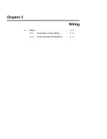
Страница 37: ...Chapter 3 Wiring 3 1 Wiring 3 3 3 1 1 Transmission Cable Wiring 3 3 3 1 2 Crimp Terminal Specifications 3 4...
Страница 38: ...Wiring FP2 Multi wire Link Unit 3 2...
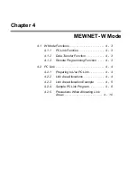
Страница 42: ...MEWNET W Mode FP2 Multi wire Link Unit 4 2...
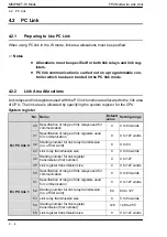
Страница 52: ...MEWNET W Mode FP2 Multi wire Link Unit 4 12 4 2 PC Link...
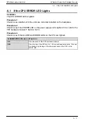
Страница 54: ...What to Check If a Problem Occurs FP2 Multi wire Link Unit A 2...
Страница 60: ...What to Check If a Problem Occurs FP2 Multi wire Link Unit A 8 A 4 What to Do If a Transmission Error Occurs...
Страница 61: ...Appendix B Dimensions...
Страница 62: ...Dimensions FP2 Multi wire Link Unit B 2...
Страница 63: ...Dimensions FP2 Multi wire Link Unit B 3 unit mm in 28 1 102 100 3 937 12 6 0 496 93 3 661...
Страница 64: ...Dimensions FP2 Multi wire Link Unit B 4...
Страница 67: ......
Страница 68: ...ARCT1F302E 2 200811 ACG M302E 2...


