ENGLISH - 5
Standard installation dimensions
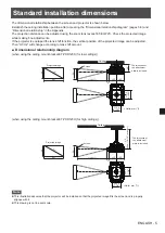
The dimensional relationship between the screen and projector is shown below.
Establish the ceiling installation position after accessing the “Dimensional relationship diagram” (pages 5-6) and
“Dimensional relationship” in the Appendix.
The projection distance can be adjusted using the zoom lens (except ET-ELW21). Check the projected image
while making fine adjustments.
If the projector is equipped the lens shift function, the vertical position of the projected image can be adjusted.
Then “H1/H2” will change according to lens shift amount.
■
Dimensional relationship diagram
(when using the ceiling mount bracket ET-PKD120S (for low ceilings))
H1
*
215.0
(8-15/32")
* The thickness of
the attachment
plate is included.
L2F
L2R
L(LW/LT)
L1
Ceiling
Projected image
<Units: mm (")>
Screen
218.0
(8-19/32")
SH
SW
SD
SH
SW
(when using the ceiling mount bracket ET-PKD120H (for high ceilings))
L3F
L3R
H2
*
(40 m
m (
1-9/16"
) increment)
200.0
(7-7/8")
200.0 (7-7/8")
* The thickness of
the attachment
plate is included.
Ceiling
Projected image
<Units: mm (")>
Screen
SH
L(LW/LT)
SW
SD
SH
SW
L1
Note
z
This illustration assumes that the projector will be installed so that the projected image fills the screen and is properly
aligned with it.
z
This drawing is not in exact scale.


