13
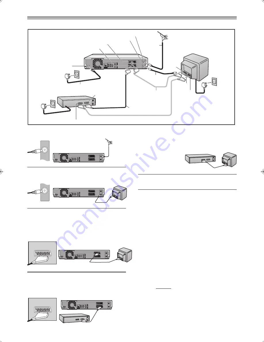
Connections (with Scart leads)
Follow the step-by-step guide below.
1
Connect the aerial to the RF Input socket of the DVD
Recorder.
2
Connect the RF lead from the RF Output socket of
the DVD Recorder to the TV aerial input socket.
3
Connect the AV1 21-pin scart socket to TV scart
socket (optional).
≥
This is necessary for Download from TV with Q Link function.
≥
If you use Panasonic TV with RGB output capability and want
to receive RGB signals, connect this unit to the AV1 socket
on the TV.
4
Connect the AV2 21-pin scart socket to the DVD
Recorder Scart Socket on your Satellite Receiver/
Digital Sat receiver. If you are not connecting a
Satellite Receiver, skip this step. (See pages 15, 58)
5
Connect the TV scart socket of your Satellite
Receiver to the AV1 scart socket of your TV
(optional). If you are not connecting a Satellite
Receiver, skip this step.
6
Plug the TV, DVD Recorder and Satellite Receiver
into the mains as shown at top of the page.
Hint
≥
Q Link offers a range of convenient functions. For example,
downloading of the tuning positions of all available television
stations into your unit’s memory if you connect the unit to your
television with a fully wired 21-pin Scart cable (not supplied).
Features similar to Q Link have different names and may not
work the same.
- [Q Link] is a registered trademark of Panasonic.
- [DATA LOGIC] is a registered trademark of Metz.
- [Easy Link] is a registered trademark of Philips.
- [Megalogic] is a registered trademark of Grundig.
- [SMARTLINK] is a registered trademark of Sony.
For details, refer to your television’s operating instructions or
consult your dealer.
≥
Unlike in most commercially available 21-pin Scart cables, all 21
pins of one plug on a fully wired 21-pin Scart cable are connected
to the matching pins on the other end of the cable.
Reference:
≥
If the TV set is equipped with a 21-pin scart socket that features
Y/C signal separation, set the “AV1 Output” to “S-Video”
(see page 63) so that you can play back with high picture quality
and use a fully-wired 21-pin Scart lead (not supplied) to connect
the DVD Recorder to the TV.
RF IN
RF OUT
OPTICAL
AV1 (TV)
AV2 (DECODER/EXT)
DIGITAL AUDIO OUT
(PCM/BIT STREAM)
R - AUDIO - L
VIDEO
S-VIDEO
R - AUDIO - L
VIDEO
S-VIDEO
A
V4 IN
OUT
1
2
3
4
5
6
6
6
Aerial
(not supplied)
Aerial Input
socket
TV [with or without Q link function]
(not supplied)
To AC Mains socket
AV2 socket
AV1 socket
RF lead
(supplied)
Necessary for
TV with Q Link
Necessary for Connecting
a Satellite Receiver
21-pin Scart socket (DVD)
21-pin Scart socket (TV)
To AC Mains socket
Satellite Receiver (not supplied)
AC Mains lead (supplied)
AC Input socket
AV2 (DECODER/EXT) 21-pin Scart socket
AV1 (TV) 21-pin Scart socket
RF Output socket
RF Input socket
Note:
21-pin Scart leads are not supplied.
RF IN
RF IN
RF OUT
OPTICAL
AV1 (TV)
AV2 (DECODER/EXT)
DIGITAL AUDIO OUT
(PCM/BIT STREAM)
R - AUDIO - L
VIDEO
S-VIDEO
R - AUDIO - L
VIDEO
S-VIDEO
AV
4
I
N
OUT
This unit
RF OUT
RF IN
RF OUT
OPTICAL
AV1 (TV)
AV2 (DECODER/EXT)
DIGITAL AUDIO OUT
(PCM/BIT STREAM)
R - AUDIO - L
VIDEO
S-VIDEO
R - AUDIO - L
VIDEO
S-VIDEO
A
V4 IN
OUT
This unit
TV
AV1 (TV)
RF IN
RF OUT
OPTICAL
AV1 (TV)
AV2 (DECODER/EXT)
DIGITAL AUDIO OUT
(PCM/BIT STREAM)
R - AUDIO - L
VIDEO
S-VIDEO
R - AUDIO - L
VIDEO
S-VIDEO
A
V
4 IN
OUT
This unit
TV
AV2(DECODER/DECODEUR/EXT)
RF IN
RF OUT
OPTICAL
AV1 (TV)
AV2 (DECODER/EXT)
DIGITAL AUDIO OUT
(PCM/BIT STREAM)
R - AUDIO - L
VIDEO
S-VIDEO
R - AUDIO - L
VIDEO
S-VIDEO
A
V4 IN
OUT
Satellite Receiver
This unit
TV
Satellite Receiver
B.book 13 ページ 2003年5月2日 金曜日 午前10時8分


