


32
13 Protection Control
13.1. Protection Control For All Operations
13.1.1.
Time Delay Safety Control
1. The compressor will not start for 3 minutes after stop of the operation.
2. This control is not applicable if the power supply is cut off and on again or after 4-way valve deices condition.
13.1.2.
30 Seconds Forced Operation
1. Once compressor starts the operation, it will not stop its operation for 30 seconds.
2. However, it can be stopped with the remote control or the Auto Switch on the indoor unit.
13.1.3.
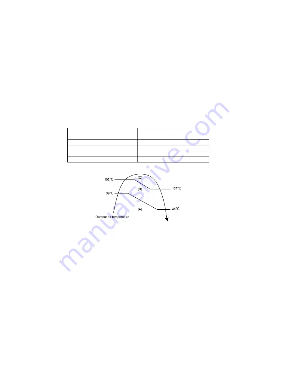
Total Running Current Control
1. When the outdoor unit total running current (AC) exceeds X value, the frequency instructed for compressor operation will be
decreased.
2. If the running current does not exceed X value for 5 seconds, the frequency instructed will be increased.
3. However, if total outdoor unit running current exceeds Y value, compressor will be stopped immediately for 3 minutes.
4. The first 30 minutes of cooling operation, (A) will be applied.
13.1.4.
IPM (Power transistor) Prevention Control
A. Overheating Prevention Control
1. When the IPM temperature rises to 110
q
C, compressor operation will stop immediately.
2. Compressor operation restarts after 3 minutes the temperature decreases to 95
q
C.
B. DC Peak Current Control
1.When electric current to IPM exceeds set value of 20.2 A, the compressor will stop operate. Then, operation will restart after
3 minutes.
2. If the set value is exceeded again more than 30 seconds after the compressor starts, the operation will restart after two
minutes.
3. If the set value exceeded again within 30 seconds after the compressor starts, the operation will restart after one minute. If
this condition repeats continuously for seven times, all indoor and outdoor relays will be cut off.
Model
TE15HK
Operation Mode
X (A)
Y (A)
Cooling/Soft Dry (A)
8.37
15.88
Cooling/Soft Dry (B)
7.87
15.88
Cooling/Soft Dry (C)
8.37
15.88
Heating
8.89
15.88
Содержание CS-TE15HKE
Страница 8: ...8 5 Dimensions 5 1 Indoor Unit...
Страница 9: ...9 5 2 Outdoor Unit...
Страница 10: ...10 6 Refrigeration Cycle Diagram...
Страница 11: ...11 7 Block Diagram...
Страница 12: ...12 8 Wiring Connection Diagram 8 1 Indoor Unit...
Страница 13: ...13 8 2 Outdoor Unit...
Страница 14: ...14 9 Electronic Circuit Diagram 9 1 Indoor Unit...
Страница 15: ...15 9 2 Outdoor Unit...
Страница 16: ...16 10 Printed Circuit Board 10 1 Indoor Unit 10 1 1 Printed Circuit Board...
Страница 17: ...17 10 2 Outdoor Unit 10 2 1 Main Printed Circuit Board...
Страница 20: ...20 3 For the embedded piping This can be used for left rear piping and left bottom piping also...
Страница 43: ...43 16 1 2 Removal of Electronic Controller...
Страница 44: ...44 16 1 3 Removal of Control Board...
Страница 45: ...45 16 1 4 Removal of Fan Motor and Cross Flow Fan...
Страница 46: ...46...
Страница 48: ...48 17 Technical Data 17 1 Operation Characteristics...
Страница 49: ...49...
Страница 50: ...50...
Страница 51: ...51...