background image

Technical Terminology & Cautions for Use

AECTB36E   201811-T

OPERATING CHARACTERISTIC

TECHNICAL NOTES ON MECHANICAL CHARACTERISTICS

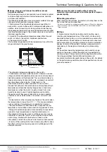
Definition of operating characteristic

The main terminological illustrations and
meanings which are used with snap-
action switches are as follows.

Center of mounting holes

FP

OF

RF

TT

MD

OT

TTP

OP

PT

TF

RP

Classification

Terminology

Symbol

Unit

Varying 

display 

method

Starting current

Force

Operating 
Force

OF

N

Max.

The force required to cause contact snap-action. It 
is expressed terms of force applied to the the 
actuator.

Release 
Force

RF

N

Min.

The force to be applied to the the actuator at the 
moment contact snaps back from operated 
position to total travel position.

Totaltravel 
Force

TF

N

Force applied to an actuator required to move from 
an operating position to a total travel position

Movement

Pretravel

PT

mm, 

degree

Max.

Distance or agree of the actuator movement from 
free position to operating position.

Overtravel

OT

mm, 

degree

Min.

The distance or degree which the actuator is 
permitted to travel after actuation without any 
damage to the switching mechanism.

Movement 
Differential

MD

mm, 

degree

Max.

The distance or degree from operating position to 
release position of the actuator.

Totaltravel

TT

mm, 

degree

The migration length or the move angle from the 
free position to total travel position of actuator

Position

Free 
Position

FP

mm, 

degree

Position of the actuator when no force is applied 
to.

Operating 
Position

OP

mm, 

degree

±

The position of the actuator when the traveling 
contacts snaps with the fixed contact.

Release 
Position

RP

mm, 

degree

The position of the actuator when the traveling 
contact snaps back from operating position to its 
original position.

Total travel 
Position

TTP

mm, 

degree

The stopping position of the actuator after total 
travel.

Actuation Force and Stroke

Adequate stroke setting is the key to high reliability. It is also
important that adequate contact force be ’maintained to ensure
high reliability. For a normally closed (NC) circuit, the driving
mechanism should be set so that the actuator is normally in the
free position. For a normally open (NO) circuit, the actuator
should be pressed to 70% to 100% of the specified stroke to
absorb possible errors.
If the stroke is set too close to the operating point (OP), this may
cause unstable contact, and in the worst case may cause
actuator damage due to inertia of the drive mechanism. It is
advisable that the stroke be adjusted with the mounting plate or
driving mechanism.

The figure at right 
shows a typical 
example of activation 
and contact forces 
varying with stroke. 
In the vicinity of the 
OP and RP, the 
contact force is 
diminished, causing 
chatter and contact 
bounce immediately 
before or after 
reversal. For this 
reason, use the 
switch while giving 
due consideration to 
this. This also causes 
the snap action 
switch to be sensitive 
to vibration or shock.

Changes in Operating Characteristics

Exercise design care so that malfunctions will not occur if the
operating characteristics vary by as much as 20% from, rated
values.
<Example>
In the OF max. 0.98N specification for FS snap-action switches,
the allowable max. is 0.98 N 

×

 (100%+20%) = 1.18 N

In the RF min. 0.15 N min. specification
the allowable min. 0.15 N 

×

 (100%–20%) = 0.12 N

Mechanical Conditions for Type Selection

Actuator type should be selected according to activation
method, activation speed, activation rate, and activation
frequency.
1) An extremely slow activation speed may cause unstable
contact transfer, possibly resulting in contact failures or contact
fusion.
2) An extremely high activation speed may cause damage to
contacts or contact response failure.

Driving Mechanism

Use of a driving mechanism which will cause physical impact to
the actuator should be avoided.

<Example>

Bad

Good

OF

RF

PT

NC

On FP

On reversal

On reversal

On OTP

NO

Stroke

Stroke

MD

OT

FP

RP

OP

TTP

Contact force

Operating force

ー 7 ー

Downloaded from

Arrow.com.

Downloaded from

Arrow.com.

Downloaded from

Arrow.com.

Downloaded from

Arrow.com.

Downloaded from

Arrow.com.

Downloaded from

Arrow.com.

Downloaded from

Arrow.com.

Содержание AV6 Series

Страница 1: ...Copying machine Printer Also for all types of equipment required for maintenance and inspections 2 SPST NO LEVER POSITION 1 Standard 2 Backward CURRENT CAPACITY reference APPLICABLE CONNECTOR Easy assembling as this switch is connector integrated Applicable connector XA connector produced by JST Mfg Co Ltd Contact SXA 001T P0 6 Housing XAP 02V 1 Connector Applicable range 100mA 1mA 0 30V 5V DC AV ...

Страница 2: ...ts 1 500 Vrms for 1 min Between each terminal and ground 1 500 Vrms for 1 min Contact resistance initial 100mΩ max by voltage drop 0 1A 6 to 8 VDC Value includes the resistance between the connector and the lead AWG28 length 50 mm Viblation resistance malfunction vibration resistance 10 to 55 Hz at single amplitude of 0 75mm Contact opening max 1msec Shock resistance malfunction shock resistance A...

Страница 3: ...7 6 3 85 7 2 5 9 5 0 08 29 2 2 4 0 05 0 1 2 4 0 05 0 1 7 7 Pin plunger type PT 0 6 Max Pin plunger type OP 8 4 0 3 10 0 Pretravel PT Max 0 6mm Movement Differential MD Max 0 1mm Overtravel OT Min 0 4mm Operating Position OP Distance from mounting hole 8 4 0 3mm CAD Data Hinge lever External dimensions 12 9 4 0 7 2 5 OP 10 0 0 08 PT 2 6 Max 2 5 0 1 5 7 9 5 0 08 29 2 2 4 0 05 0 1 2 4 0 05 0 1 7 7 10...

Страница 4: ...ever position Standard Pretravel PT Max 2 6mm Movement Differential MD Max 0 8mm Overtravel OT Min 1 2mm Operating Position OP Distance from mounting hole 12 2 0 8mm Pretravel PT Max 1 4mm Movement Differential MD Max 0 6mm Overtravel OT Min 0 7mm Operating Position OP Distance from mounting hole 11 3 0 6mm Pretravel PT Max 2 6mm Movement Differential MD Max 0 8mm Overtravel OT Min 1 2mm Operating...

Страница 5: ...than the specified connector or solder the terminals directly 2 Make sure leads are arranged so that no constant force is applied to them when the connectors are mated 3 Keep the connector straight when inserting it If it is inserted at an angle it may snag near the entrance or it may be inserted too forcefully 4 Problems thought to be caused by the XA connector which is specified as conforming to...

Страница 6: ...d The life test is performed at a switching frequency of 20 times minute and operating speed of 100 mm second at the regular cam Contact form This refers to the components determining the type of application which make up the electrical input output circuits in the contact Insulation resistance Resistance between non continuous terminals each terminal and other exposed metal parts and between each...

Страница 7: ...orce be maintained to ensure high reliability For a normally closed NC circuit the driving mechanism should be set so that the actuator is normally in the free position For a normally open NO circuit the actuator should be pressed to 70 to 100 of the specified stroke to absorb possible errors If the stroke is set too close to the operating point OP this may cause unstable contact and in the worst ...

Страница 8: ...ct resistance across COM and NO terminals is measured in the total travel position 7 To prevent contact welding failure be sure to use a serial resistance for each capacitive load 8 If snap action switch operation is synchronized with the AC supply phase this may cause shortened electrical life contact fusion failure contact transfer or other reliability problems Small current and voltage applicat...

Страница 9: ... the section CAUTIONS FOR USE for each product Avoid using in a silicon atmosphere Avoid using organic silicon rubber adhesives sealing compounds oil grease and wires in a silicon atmosphere Please consult us when using under the following conditions 1 Environments where hydrogen sulfide or other corrosive gases are present 2 Environments where gasoline thinner or other flammable explosive gases a...

Страница 10: ...ods of time Storage for extended periods of time including transportation periods at high temperatures or high humidity levels or in atmospheres with organic gases or sulfide gases may cause a sulfide film or oxide film to form on the surfaces of the contacts and or it may interfere with the functions Check out the atmosphere in which the units are to be stored and transported In terms of the pack...

Страница 11: ...ing unit Simulated roller lever Large Medium Small Possible Tip of hinge lever is bent into a semi circle enabling use as a simple roller type Leaf lever Large Large Small Excellent Play in lever is used to assure maximum stroke Construction provides for space where lever is attached for outstanding resistance to freezing Hinge roller lever Large Medium Small Possible This is a hinge lever with a ...

Страница 12: ...rrow com Downloaded from Arrow com Downloaded from Arrow com Downloaded from Arrow com Downloaded from Arrow com Downloaded from Arrow com Downloaded from Arrow com Downloaded from Arrow com Downloaded from Arrow com Downloaded from Arrow com Downloaded from Arrow com ...

Отзывы: