background image

11

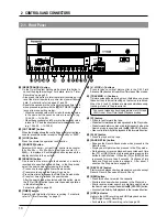
2-2  Display

2  CONTROLS AND CONNECTORS

2

3

4

5

1

6

7

8

9

13

12

11

10

13

14

1

Operation mode display
Shows the operation modes.

Playback

Recording

Rewind

Fast-
forward

Timelapse 
playback

Still

Record-
pause

Reverse step 
slow playback

Field-by-field 
playback

Rewind 
search

Fast-forward 
search

Reverse 
playback

5

Recording/playback speed display
• Normally shows the recording/playback speed mode set

with the [TIME MODE] button.

• Shows the following indications in the Alarm Search mode.

During alarm search:  Shows the specified alarm number
(example: AL12)
During alarm scan: Shows the alarm scan mode (ALSC).
During date/time search: Shows the specified date and
time (example 2310).

• Shows setting details in menu switch setting.
• When an error occurs, the error indication “E-**” blinks (if

the menu switch <WARNING> on the <FRONT DISPLAY>
screen is set to “ON”).
For error indications, refer to page 53.

6

[TIMER] indication
Lights during timer recording programming/operation.

7

 [REPEAT] indication

When <REPEAT REC> in the <VTR MODE> menu is set
to  “ON”, this indication is shown. When <TAPE END
MODE> in the <ALARM/SENSOR MODE> menu is set to
“STOP” and the Repeat Record mode is engaged, the
[REPEAT] indication goes out if alarm recording or sensor
recording takes place.

8

[OVERLAP] indication
Blinks when programs scheduled for timer recording overlap.

9

Timer program number
All programmed timer recording numbers light.
During timer recording, the number of the program being
recorded blinks.  When the timer recording ends, this
number goes out.

0

[AL] (alarm) indication
Shown during alarm recording or sensor recording.
Blinks when alarm recording or sensor recording ends.

!

[S-VHS] indication
Lights when a S-VHS cassette is loaded. In the playback
mode, it lights during playback of a tape recorded in the S-
VHS mode.

@

[LOCK] indication
Lights when the operation lock function is activated.

#

[AL REC] (alarm recording) indication
Lights when the menu switch <REC MODE> on the <ALARM/
SENSOR MODE> screen is set to “ALARM” or “AL/
SENSOR”.

$

[SENSOR REC] (sensor recording) indication
Lights when the menu switch <REC MODE> on the <ALARM/
SENSOR MODE> screen is set to “SENSOR” or “AL/
SENSOR”.

     * (

) mark in the Rec/Pause mode is shown in red.

2

 Cassette indication

Lights when a cassette is loaded. Blinks when a cassette
is being ejected.

3

[SP/EP] indication
Shows the standard (SP) mode or extended (EP) mode
during recording/playback.  During ordinary timelapse
recording/playback, the [SP] indication is shown.
The [EP] indication is shown during recording in the HDR
(High-Density Record) mode or during playback of a tape
section recorded in the HDR mode.

4

Tape counter/clock indication
• Shows the current time (hour: minute: second), tape

control counter (00H 00M 00S — 23H 59M 59S) or tape
reel counter (0 — 9999) when the operating mode is on.

   The display can be selected with the [DISPLAY] button.

Shows the current time when the operating mode is off.
When a cassette is ejected, the tape control counter and
tape reel counter are reset automatically.

• When the cassette is rewound to the beginning in the

Repeat Recording or Auto Rewind mode using the counter
end output function, the tape control counter and tape
reel counter are reset.

• The control and reel counter counts slowly in the Timelapse

mode.

• In the timelapse mode, the control counter shows the time

equivalent to that shown when a tape is played back in the
2H or 6H mode.
(Example: The control counter advances 1 second for
about 8 minutes in the 960H ordinary timelapse mode.)

• During date/time search setting and operation, “td” is

shown in place of the seconds.

• Shows the setting item during menu switch setting.

Содержание AG-TL950P

Страница 1: ...ACK AND SPECIAL EFFECTS PLAYBACK TROUBLE SHOOTING APPENDIXES Operating Instructions Time Lapse Video Cassette Recorder Before attempting to connect operate or adjust this product please read these instructions completely P Printed in Japan VQT9726 P LLT0004 001A Professional Industrial video Model AG ...

Страница 2: ...ilisé que sur du courant alternatif en 120 V ATTENTION Afin d éviter tout resque d incendie ou d électrocution ne pas utiliser d autres sources d alimentation électrique REMARQUE La plaque d identification numéro de série se trouve sur le panneau arrière de l appareil Le symbole de l éclair à l intérieur d un triangle équilatéral est destiné à alerter l utilisateur sur la présence d une tension da...

Страница 3: ...tion is activated all operation buttons are disabled OPERATION LOCK 1 Engage the mode you want to lock such as the Rec or Play mode 2 While pressing the LOCK button press the TIME MODE button LOCK is shown on the display indicating that the Operation Lock mode is engaged 3 To unlock the VCR press the TIME MODE button while pressing the LOCK button The LOCK indication on the display disappears and ...

Страница 4: ...4 ...

Страница 5: ...xternal VCR Activation Signal 44 6 9 How to Restore Recording After Power Failure 45 6 10 External Timer Recording 45 6 11 Tape End Buzzer 45 7 PLAYBACK AND SPECIAL EFFECTS PLAYBACK 7 1 Preparation 46 7 2 Playback 46 7 3 Special Effects Playback 47 Still Field Advance Reverse Playback 47 Shuttle Search 48 7 4 Alarm Search Date and Time Search 49 7 5 Repeat Playback 51 7 6 Counter Memory Function 5...

Страница 6: ...Recording Standby or Operating Off mode the Record mode is automatically engaged 5 Time date generator Superimposes date month year hour minute and second on the image during recording Also allows you to display the number of alarms alarm time and the number of the power failures on a monitor 5 Timer recording function Up to 8 programs can be set for daily weekly or weekday timer recording You can...

Страница 7: ...tically ejects the cassette and the error indication E 08 blinks on the display Operation is disabled until the E 08 indication on the display goes out Periodic Maintenance Check or replace the following mechanical parts according to the running time Head drum Video tape 1 INTRODUCTION Cleaning 䡬 Check or replace as required 䢇 Replace Maintenance requirements may vary depending on the operating en...

Страница 8: ... long periods of time which means that a durable tape is required When using VHS tapes do not use tapes with recording times of more than 120 minutes T 160 T 180 etc For best results use a T 120 tape If any problems are found after inspection turn the power off unplug the mains plug from the socket and contact your Panasonic dealer 1 5 Regarding S VHS ET Recording Accidentally inserting a tape rec...

Страница 9: ... timer program setting and menu switch setting 7 5 1 2 3 4 9 8 6 REC EJECT REC REVIEW REC PAUSE STILL MENU TIME MODE SET ON SCREEN SHIFT REW PLAY FF REV PLAY TRACKING V LOCK TIMER SEARCH COUNTER LOCK CNT RESET RESET CANCEL STOP REV ADV FWD ADV AG 11 10 12 POWER POWER HDR S VHS tape VHS tape HDR recording HDR recording Playback speed On Off On Off 2H 2H 2H 2H Standard 6H 6H 6H 6H 3x L12H 12 hour SP...

Страница 10: ...CTORS 14 15 16 17 20 19 13 26 25 24 23 22 21 18 REC EJECT REC REVIEW REC PAUSE STILL MENU TIME MODE SET ON SCREEN SHIFT REW PLAY FF REV PLAY TRACKING V LOCK TIMER SEARCH COUNTER LOCK CNT RESET RESET CANCEL STOP REV ADV FWD ADV POWER POWER HDR AG V LOCK buttons Press to reduce vertical picture jitter in the Still Field Advance Playback and Linear Slow Timelapse Play modes TRACKING buttons If pictur...

Страница 11: ...is loaded In the playback mode it lights during playback of a tape recorded in the S VHS mode LOCK indication Lights when the operation lock function is activated AL REC alarm recording indication Lightswhenthemenuswitch RECMODE onthe ALARM SENSOR MODE screen is set to ALARM or AL SENSOR SENSOR REC sensor recording indication Lightswhenthemenuswitch RECMODE onthe ALARM SENSOR MODE screen is set to...

Страница 12: ... from both the microphone connector and the audio input connector audio signals are mixed and recorded 4 AUDIO IN audio input connector Phono Receives audio signals from a connected audio source 5 AUDIO OUT audio output connector Phono Outputs audio signals No signal is output in the Timelapse Recording Playback mode 6 VIDEO IN video input connector BNC Receives composite video signals from a conn...

Страница 13: ... Outputs the clock reset signal The clock reset signal is output in the following cases When the internal clock is at 0 00 or 12 00 When this unit is connected to another AG TL950P s CLOCK RESET IN terminal the other VCR s clock can be set to the clock in this unit However the time difference should be within 30 seconds q SERIES REC IN series recording VCR activation signal input terminal Receives...

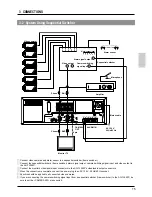
Страница 14: ...he AG TL950P s video audio output connectors 2 Connect the video camera s video output connector to the AG TL950P s video input connector 3 Input audio signals to the audio input connectors via an amplifier 4 When connecting an alarm sensor connect it to the AG TL950P s alarm input terminal 5 When the connection is complete connect the power plug to an AC 120 V 50 Hz 60 Hz socket Mains cable M3 5 ...

Страница 15: ... cable BNC BNC Phono Phono 4pin 1 Connect video cameras and alarm sensor to a sequential switcher frame switcher 2 Connect the sequential switcher s frame switcher alarm signal output camera switching signal input and video output to the AG TL950P 3 Connect the monitor s video audio input connectors to the AG TL950P s video audio output connectors 4 When the connection is complete connect the powe...

Страница 16: ...se appropriately rated devices ALARM COM IN Sequential switcher alarm output terminal ALARM REC OUT COM Switch ALARM RESET External interface Alarm lamp COM Vcc 5V 12V Vcc ALARM RESET Switch COM CAM SW OUT Sequential switcher camera switching signal input TAPE END OUT tape end output terminal WARNING OUT warning signal output terminal COM WARNING OUT External interface Alarm lamp COM TAPE END OUT ...

Страница 17: ...EEN buttons The type of data shown and display brightness can be selected on the ON SCREEN FRONT DISPLAY MODE screen ON SCREEN t button ON SCREEN 7 button Preparation 5 Connect the video output connector of this unit to the monitor s video input connector 1 Turn on the monitor and VCR 2 When a video signal from a camera is input to the video input connector on screen data is superimposed on the pi...

Страница 18: ...s such as V Pulse ON OFF HDR recording counter memory function and repeat recording playback 5 SRI EXT MODE VCR s display SRi ET For setting series recording or automatic recording with an external signal 5 ALARM SENSOR MODE VCR s display AL 5EN For setting alarm recording or sensor recording operation 5 BUZZER IN OUT VCR s display BU22iO Turn ON OFF buzzers such as the tape end buzzer and alarm s...

Страница 19: ...utton The CLOCK SET screen is shown The cursor shows the TIME setting item and the hour digit blinks Check that DAYLIGHT SAVINGS on the last line is set to OFF 5 Set the hour by pressing the SET button This VCR uses the 24 hour system Press the SET button to increase the numerical value and the SET button to decrease it same for minute month day and year setting 5 During summer time period set the...

Страница 20: ...r on the HOUR METER on the main menu 4 Press the SET button to show the hour meter drum rotating time on the monitor 5 Press the MENU button twice to restore the normal screen Notes If the power plug has been disconnected from an AC outlet for a long time make sure the set time is correct before using the unit Clock time may be affected by environmental factors When the built in backup battery cap...

Страница 21: ...CALL POWER LOSS 4 Press the SET button to display the ALARM RECALL POWER LOSS screen 5 Press the SHIFT 7 button to set the cursor on the item you want to display ALARM LIST or POWER LOSS LIST 6 Press the SET button to display the alarm or power loss list Alarm list Up to 8 alarms are shown When 9 or more alarms are input the most recent data will replace the earliest data beginning with the second...

Страница 22: ... SEARCH COUNTER LOCK CNT RESET RESET CANCEL STOP REV ADV FWD ADV POWER HDR POWER AG 4 6 Menu Switch Setting 4 ON SCREEN MENU SWITCHES You can customize the VCR s functions to suit the requirements of your application using the four menu switch setting screens accessible from the main menu screen ON SCREEN F DISPLAY MODE VIDEO VTR MODE SRI EXT ALARM SENSOR MODE BUZZER IN OUT Each menu switch settin...

Страница 23: ... T MODE ON OFF ON OFF O5D 4 ALARM CNT ON OFF ON OFF Sets whether or not the number of alarms is shown on screen ON Shown OFF Not shown O5D 5 O5D 6 FRONT REC TALLY ON DISPLAY OFF ON OFF FDiP 1 Sets whether or not a warning indication error code display is shown when a problem occurs ON Shown OFF Not shown Sets whether or not the REC indicator lights in the Record mode ON Lights OFF Does not light S...

Страница 24: ...OFF ON Sets whether or not Recording Check is automatically performed at the beginning of a tape in the Repeat Recording mode OFF Automatic recording check function is disabled ON Automatic recording check function is enabled Sets whether or not the counter memory function is activated OFF The counter memory function is not activated ON The counter memory function is activated When the tape reel c...

Страница 25: ...Operating Off mode recording starts in the 2H 6H L12H L18H L24H 24H 48H NORMAL mode OFF Alarm or sensor recording is not executed ALARM Alarm recording is executed SENSOR Sensor recording is executed AL SENSOR Both alarm and sensor recording are executed AL SE 1 SRI EXT SRI EXT REC OFF MODE SERIES EXT OFF SERi EiT Selects series recording or automatic recording with an external VCR activation sign...

Страница 26: ...n the SRI EXT MODE screen is reached When the mode is changed by pressing the REW button EJECT button or OPERATE button the buzzer sound stops BUZZER TAPE END OFF ON OFF ON BU 22 1 OFF STOP DURATION 5 SEC 10 SEC 15 SEC 30 SEC 60 SEC 120 SEC 180 SEC CONTINUE MANUAL 5 180 CONT nANU ALARM SENSOR MODE Selects the recording duration for alarm or sensor recording 5 180 SEC Alarm or sensor recording is p...

Страница 27: ...ing mode is automatically switched on and the cassette is ejected Once the cassette is unloaded the operating mode turns off again automatically If the Timer Recording Standby mode is engaged TIMER indication is shown on the display the cassette will not be ejected when the EJECT button is pressed To unload the cassette press the TIMER button to release the Timer Recording Standby mode then press ...

Страница 28: ... 15 48 hour timelapse 12 24 36 48 Impossible 72H 0 6 0 2 72 hour timelapse 18 36 54 72 Impossible 84H 0 7 0 25 84 hour timelapse 21 42 63 84 Impossible 120H 1 0 35 120 hour timelapse 30 60 90 120 Impossible 168H 1 4 0 5 168 hour timelapse 48 96 144 168 Impossible 240H 2 0 7 240 hour timelapse 60 120 180 240 Impossible 480H 4 1 35 480 hour timelapse 120 240 360 480 Impossible 960H 8 2 7 960 hour ti...

Страница 29: ...s set to ON repeat recording takes place regardless of the setting of this switch REPEAT REC Set to ON to perform repeat recording For details refer to 6 7 Repeat Recording on page 43 AUTO REC CHECK Set to ON to perform Recording Check automatically at the beginning of a tape in the Repeat Recording mode 5 SRI EXT MODE SRI EXT REC Set to SERIES to perform series recording For details refer to 6 6 ...

Страница 30: ...CNT RESET RESET CANCEL STOP REV ADV FWD ADV POWER HDR POWER REC EJECT REC REVIEW REC PAUSE STILL MENU TIME MODE SET ON SCREEN SHIFT REW PLAY FF REV PLAY TRACKING V LOCK TIMER SEARCH COUNTER LOCK CNT RESET RESET CANCEL STOP REV ADV FWD ADV AG POWER HDR POWER 1 Press the POWER button to turn the operating mode on The POWER indicator lights 2 Select the recording speed mode with the TIME MODE button ...

Страница 31: ...main menu Then press the SET button The VIDEO VTR MODE menu is shown on the monitor 2 Press the SHIFT 7 button to put the cursor on HIGH DENSITY REC 3 Press the SET button to set HIGH DENSITY REC to ON 4 Press the MENU button to restore the main menu screen Notes Timer programming is not possible if the date and time are not set If you select program timer or holiday setting from the main menu whe...

Страница 32: ...stop time When the stop time is earlier than the start time or the same as the start time T is added to the beginning of the stop time showing that the stop time is for the next day 0 Set the recording speed mode H D 24 Press the SHIFT f button so that SPD blinks and press the SET button to set the recording speed to H D 24 When the HIGH DENSITY REC mode is selected H D is shown for SPD Set the pr...

Страница 33: ...ms lasting for more than 24 hours can only be set on the seventh line 3 Press the SET button to set the day of the week to FRI and press the SHIFT f button Hour for the start time blinks 4 Press the SET button to set the hour of the start time to 21 and press the SHIFT f button Minute for the start time blinks 5 Press the SET button to set the minute of the start time to 00 and press the SHIFT f b...

Страница 34: ...SET button 4 Press the SHIFT f button so that the minute for the start time blinks and set minute to 00 with the SET button 5 Press the SHIFT f button and SET button to set the hour of the stop time to 17 the minute of the stop time to 00 the recording speed to H D48 and PGM to ON 6 Set the days of the week when timer recording is to be executed Monday Wednesday Saturday Set the days with DAILY SE...

Страница 35: ...he stop time to 00 and press the SHIFT f button T is shown at the beginning of the stop time When the stop time is earlier than the start time or the same as the start time the stop time is assumed to be the next day and T is added to the beginning of the stop time 7 Press the SHIFT f button and SET button to set the minute of the stop time to 00 the recording speed to 960 and PGM to ON 8 Set the ...

Страница 36: ...u want to cancel 5 Press the RESET CANCEL button The specified timer recording program is canceled 6 Press the MENU button twice The normal screen is restored TIMER button SET button SHIFT f button SHIFT 7 button SET button MENU button RESET CANCEL button To modify timer programs 1 Press the TIMER button so that the TIMER indication goes out on the display 2 Turn on the VCR and monitor 3 Press the...

Страница 37: ...ers are not displayed for holiday timer recording programs 5 When the timer recording mode is engaged after the start time has passed When a power failure occurs within the set times and power is restored Timer recording starts within the set times If holiday timer and program timer settings overlap the holiday timer setting has priority and starts When program timer settings overlap the program w...

Страница 38: ...rts from that point 6 RECORDING On screen ALARM indication Extinguished Extinguished Shown Shown Extinguished Extinguished Display AL indication Lit Lit Blinking Blinking Record mode Timelapse mode Timelapse mode Timelapse mode Timelapse recording Timelapse recording Timelapse recording Alarm recording Alarm recording Alarm signal input Alarm signal input 2H 6H L12H L18H L24H 24H 48H NORMAL 2H 6H ...

Страница 39: ...a malfunction Connect an alarm sensor to the rear panel s alarm input terminal Preparation 1 Press the POWER button to turn the operating mode on 2 Open the main menu s ALARM SENSOR MODE and set the alarm recording related menu switches 1 REC MODE Set to ALARM or AL SENSOR to activate alarm recording When set to AL SENSOR both alarm recording and sensor recording will be performed The ALARM indica...

Страница 40: ...u switches 5 Setting the alarm buzzer Set the menu switch AL SENSOR IN in BUZZER to ON to sound the alarm buzzer during sensor recording 5 Setting the on screen brightness and display items Select the monitor display setting with the menu switch On screen information is recorded together with the video signals You can change the on screen display position with the ON SCREEN 7 f buttons on the fron...

Страница 41: ... to the monitor s video and audio input connectors Connections Video input signal First VCR Second VCR Last VCR Video output Rear panel 5Normally the next VCR starts recording when the tape ends If the menu switch counter end output function is on a series recording signal is output when the selected tape reel counter value is passed and the next VCR starts recording Select the counter end value f...

Страница 42: ...NING OUT CLOCK RESET IN SERIES REC IN SERIES REC OUT CLOCK RESETOUT COM WARNING OUT CLOCK RESET IN SERIES REC IN SERIES REC OUT CLOCK RESETOUT First VCR Second VCR Connect audio and video terminals as shown in the connection diagram on page 41 6 RECORDING Non stop continuous series recording The series recording function allows you to record indefinitely using two VCRs Recording alternates between...

Страница 43: ... switch in VTR MODE to ON 5 Operation of the automatic recording check function Recording is performed from the beginning of the tape for several seconds during repeat recording Then the recorded section is automatically played back to check whether or not the signals have been recorded properly If the recording is satisfactory recording resumes If the recording is unsatisfactory the heads are cle...

Страница 44: ...ry Operation 1 Set the SRI EXT REC menu switch in SRI EXT MODE to EXT to use the external recording function Use the EXT REC END menu switch to select the mode engaged when externally activated recording ends When set to NORMAL the VCR enters the Stop mode When set to POWER OFF the operating mode is turned off 2 Press the MENU button to set the on screen display to the time date display 3 Load a c...

Страница 45: ...d by connecting the AG TL950P to an external timer 2 Set the EXT TIMER REC menu switch in VTR MODE to ON Power is supplied from the external timer at the specified time and recording starts Recording is performed at the preset recording speed If alarm recording or sensor recording is executed before the power is supplied the Alarm Record mode or Sensor Record mode is released and normal recording ...

Страница 46: ... 2H is shown on the display Cassettes recorded in the 6H or HDR Timelapse mode are played back in the 6H EP mode 6H is shown on the display To stop playback 5 Press the STOP button The tape stops and the Stop mode is engaged 7 1 Preparation 7 2 Playback Connection Connect the output connectors on the rear panel correctly Menu switch setting Set the menu switches in VIDEO VTR MODE as required 5 DET...

Страница 47: ...ton or REW button is pressed for more than 2 seconds the picture is advanced or reversed continuously field by field continuous field advance playback 3 Press the PAUSE STILL button in the Continuous Field Advance Play mode to restore the Still mode Press the PLAY button to restore normal playback In the Continuous Field Advance Play mode no sound is output When continuous field advance playback c...

Страница 48: ... search Press the FF button during play The fast forward search indicator is shown on the display and the Fast Forward Shuttle Search mode is engaged 7 PLAYBACK AND SPECIAL EFFECTS PLAYBACK The operation varies depending on how the FF or REW button is pressed Refer to the table below for details Operation of the REW and FF buttons Tape recorded in the 2H SP mode or the ordinary Timelapse mode 7 ti...

Страница 49: ...nction correctly The recording duration must be equivalent to at least 5 seconds at Standard 2H or EP 6H speed Example In the 960 hour normal timelapse mode the recording time should be 40 minutes or more Alarm search A specified alarm recording is searched and the Stop mode is engaged 1 Press the SEARCH button once in the Stop mode The VCR enters the Alarm Search mode and the alarm search setting...

Страница 50: ...W FF button whichever is opposite to the current tape running direction When the end or beginning of the tape is reached during alarm search or alarm scan the mode is canceled and the Stop mode is engaged VCR s display Date time search setting screen Time setting Date time search A section recorded at a specified date and time is searched and the Stop mode is engaged 1 Press the SEARCH button thre...

Страница 51: ...o rewind When the tape ends during recording playback or forward search the VCR automatically rewinds the tape to the start and enters the Stop mode To auto rewind the tape set the AUTO REW menu switch in VTR MODE to ON 7 6 Counter Memory Function VIDEO VTR MODE When the counter memory function is ON the VCR automatically enters the Stop mode when the control tape counter reaches 00 00 00 or when ...

Страница 52: ... jitter When noise appears in the picture in the Play Field Advance mode Tracking adjustment is possible in the following modes 2H SP 6H EP L18H and timelapse play mode Field advance play 5 Press either the TRACKING button until picture noise is eliminated or minimized To return to the Tracking Preset mode press the and buttons simultaneously V LOCK buttons TRACKING buttons When the picture is dis...

Страница 53: ... 11 during recording When an error indication appears or the buzzer sounds turn the operating mode on again to clear the error indication and buzzer sound E 01 to E07 When the error indication E is shown turning the operating mode on again may not clear the problem In this case consult your local Panasonic dealer BUZZER screen Buzzer sound VCR operation The operating mode is turned off The operati...

Страница 54: ...l mode and Field Advance mode Noise appears in part of the playback picture When the cassette is played back the picture becomes rough or disappears No sound is heard during playback Recording is impossible Timer recording is not working The clock cannot be set Tape running sound is heard in the Record Play FF and REW modes The time date is not shown Auto REW and repeat recording are not possible ...

Страница 55: ...3 h 28 m 1 h 57 m 39 m 0 m 48H 48H 49 h 10 m 42 h 58 m 37 h 8 m 31 h 40 m 26 h 35 m 21 h 53 m 17 h 32 m 13 h 34 m 9 h 59 m 6 h 45 m 3 h 54 m 1 h 26 m 0 m 72H 72H 73 h 45 m 64 h 27 m 55 h 42 m 47 h 31 m 39 h 53 m 32 h 49 m 26 h 18 m 20 h 21 m 14 h 58 m 10 h 8 m 5 h 52 m 2 h 9 m 0 m 120H 120H 122 h 56 m 107 h 25 m 92 h 51 m 79 h 12 m 66 h 29 m 54 h 42 m 43 h 51 m 33 h 56 m 24 h 57 m 16 h 54 m 9 h 47...

Страница 56: ...round level Output at ground level LV 0 V CLOCK RESET IN Clock reset input Input at ground level About 100 ms About 100 ms LV 0 V CLOCK RESET OUT Clock reset output Output at ground level Over 2 5 s LV 0 V HV 5 V HV 5 V HV 5 V HV 5 V SERIES REC IN Series recording signal input Input at ground level 2 5 s to 3 s LV 0 V SERIES REC OUT Series recording signal output Output at ground level External re...

Страница 57: ...4 24 48 72 84 120 168 240 480 960 hours However L12 L18 L24 can only be selected when an S VHS tape is used Timelapse mode field recording Within about 4 minutes with T 120 cassette AC 120 V 50 Hz 60 Hz 19 watts 360 W x 115 H x 361 D mm Approx 5 5 kg 5 C to 40 C 35 RH or more 80 RH or less 20 C to 60 C LINE 1 0 Vp p 75 ohms unbalanced BNC S VIDEO Y 1 0 Vp p 75 ohms unbalanced C 0 286 Vp p 75 ohms ...

Страница 58: ...x 201 348 7372 Western Zone Office 6550 Katella Ave Panazip 17A 5 Cypress CA 90630 714 373 7840 Fax 714 373 7242 Industrial Medical Group Executive Office One Panasonic Way Panazip 4D 4 Secaucus New Jersey 07094 Panasonic Canada Inc 5770 Ambler Drive Mississauga Ontario L4W 2T3 905 624 5010 Panasonic Sales Company Division of Matsushita Electric of Puerto Rico Inc San Gabriel Industrial Park 65th ...

Отзывы: