Page 41
TU2506
ǀ
TU2807V
US
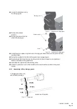
Loosen the clamping nuts on
the change gears.
Fig.4-9:
Attachment of change gears
Remove the slotted
washers.
Remove the screw from the
shaft of the feed gear.
Fig.4-10:
Attachment of change gears
Install the gear couples using the feed or change gear table and secure the gears onto the
quadrant again.
Swing the quadrant to the left until the gears have engaged again.
Readjust gear flank clearance by inserting a normal sheet of paper as an adjusting or
distance aid between the gearwheels.
Immobilise the quadrant with the locking screw.
Attach the protective cover of the headstock and reconnect the machine to the power
supply.
4.10
Assembly of the change gears
Fig.4-11: Change gear
Clamping nuts
Slotted washer
Screw
Z1
Z2 (B)
Z4 (C)
Z3 (D)
lead screw 10 tpi
pitch
1.change gear (drive unit)
with 40 teeth, standard
L (E)
Содержание TU 2506
Страница 1: ...US Item No 9684509 Operating manual Version 2 2 2 Lathe...
Страница 28: ...Page 28 TU2506 TU2807V US 3 7 2 Chuck flange TU2506 TU2807V Fig 3 1 Chuck flange TU2506 TU2807V Unit mm...
Страница 74: ...Page 74 TU2506 US...
Страница 92: ...Page 92 TU2506 TU2807V US 8 Wiring diagrams 8 1 TU2506 Fig 8 1 Wiring diagram TU2506...
Страница 93: ...Page 93 TU2506 TU2807V US 8 2 TU2807V 230V Fig 8 2 Wiring diagram TU2807V...
Страница 98: ...Page 98 TU2506 TU2807V US...


