3
SAFETY RULES (CONTINUED)
TOOL SHOULD BE MAINTAINED
•
Always unplug tool prior to inspection.
•
Read operating instructions manual for specific maintaining
and adjusting procedures.
•
Keep tool lubricated.
•
Use sharp cutters and keep the tool clean for safest operation.
•
Remove adjusting tools. Form the habit of checking that adjust-
ing tools are removed before turning on the machine.
•
Keep all parts in working order. Check to determine that the
guard or other parts will operate properly and perform their
intended function.
•
Check for damaged parts. Check for alignment of moving parts,
binding, breakage, mounting and any other condition that may
affect a tool’s operation.
•
Damaged parts should be properly repaired or replaced. Do not
perform makeshift repairs. (Use the parts list provided to order
replacement parts.)
KNOW HOW TO USE TOOL
•
Use the right tool for the job. Do not force tool or attachment
to do a job for which it was not designed.
•
Disconnect tool when changing accessories such as bits, cut-
ters and the like.
•
Avoid accidental start-up. Make sure switch is in OFF position
before plugging in.
•
Do not force tool. It will work most efficiently at the rate for
which it was designed.
•
Handle workpiece correctly. Secure work with clamps or vise.
Leave hands free to operate machine, Protect hands from
possible injury.
•
Never leave a tool running unattended. Turn the power off and
do not leave tool until it comes to a complete stop.
•
Do not overreach. Keep proper footing and balance.
•
Never stand on tool. Serious injury could occur if tool is tipped
or if cutter is unintentionally contacted.
•
Keep hands away from moving parts and cutting surfaces.
•
Know your tool. Learn its operation, application and specific
limitations.
•
Feed work into a bit or cutter against the direction of rotation
of bit or cutter.
•
Turn the machine off if it jams. A cutter jams when it digs too
deeply into the workpiece. (The motor force keeps it stuck in
workpiece.)
•
Use recommended accessories. Refer to page 9. Use of improp-
er accessories may cause risk of injury to persons.
•
Clamp workpiece or brace against column to prevent rotation.
•
Use recommended speed for drill accessory and workpiece
material.
WARNING:
Think Safety! Safety is a combination of operator com-
mon sense and alertness at all times when drill press is being used.
ASSEMBLY
MOUNT DRILL CHUCK AND ARBOR
Refer to Figure 5.
•
Be sure spindle taper, arbor taper and chuck taper are clean
and dry.
•
Insert arbor into spindle, push arbor into spindle and twist
arbor slightly to release air trapped in taper. Make sure tang of
arbor seats properly into spindle.
•
Mount chuck onto arbor, push chuck over arbor and twist
chuck slightly to release air trapped in taper.
•
Place a block of wood on table, below chuck, and firmly pull
quill feed handle to securely seat chuck and arbor into spindle.
INSTALLATION
Refer to Figures 1, 2 and 3.
MOUNT DRILL PRESS
•
Drill press must be mounted to flat level surface. Use shims or
machine mounts if necessary. Do not mount drill press in direct
sunlight.
•
Be sure to bolt drill press to floor or bench securely to prevent
tipping and minimize vibration.
•
Tighten all nuts and bolts that may have loosened during
shipment.
POWER SOURCE
Drill press requires a 115/230 volt, 60 Hz power source.
To use the drill press with a 230V power supply, have a qualified
electrician attach a 230 volt, 20/30A three-prong plug onto drill
press line cord.
The motor is designed for operation on the voltage an frequency
specified. Normal loads will be handled safely on voltages not
more than 10% above or below the specified voltage.
Running the unit on voltages which are not within the range may
cause overheating and motor burn out. Heavy loads require that the
voltage at motor terminals be no less than the voltage specified.
GROUNDING INSTRUCTIONS
WARNING:
Improper connection of equipment grounding con-
ductor can result in the risk of electrical shock. Equipment should
be grounded while in use to protect operator from electrical
shock.
Check with a qualified electrician if grounding instructions are not
understood or if in doubt as to whether the tool is properly
grounded.
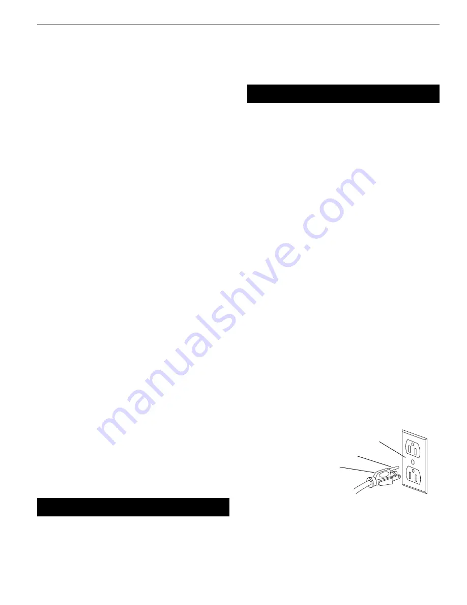
This tool is equipped with an approved 3-conductor cord rated up
to 300V and a 3-prong grounding type plug rated at 115V (See
Figure 1) for your protection against shock hazards.
Grounding plug should be plugged directly into a properly
installed and grounded 3-prong grounding-type receptacle, as
shown (Figure 1).
Do not remove or alter grounding prong in any manner. In the
event of a malfunction or breakdown, grounding provides a path
of least resistance for electrical shock.
WARNING:
Do not permit fingers to touch the terminals of plug
when installing or removing from outlet.
Plug must be plugged into matching outlet that is properly
installed and grounded in accordance with all local codes and
ordinances. Do not modify plug provided. If it will not fit in outlet,
have proper outlet installed by a qualified electrician.
Palmgren Operating Manual & Parts List
80329
Figure 1 – 3-Prong Receptacle
Properly Grounded Outlet
Grounding Prong
3-Prong Plug


