6
Gate and Platform Installation
Revision 1.3
- 16 -
6
Gate and Platform Installation
6.1
Frame Installation
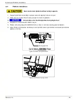
Never work under platform without safety supports
1. Unfold platform and clamp forklift forks, overhead crane or equivalent to platform
2. Raise lift gate by using forklift, overhead crane or equivalent and align front edge of platform to back
edge of bed extension leaving approx. 3/16 gap. Place it against the temporary channel, flush with
the body.
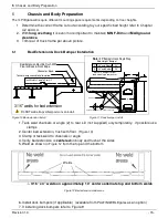
3. Use floor jack or equiv. to swing frame assembly up to proper “F” dimension per Figure 13.
4. Use second jack or pry bar at roll over wheel bracket to set horizontal rollover wheel bracket.
a. 12 V power supply needed for release pressure on lift cylinders valves, if necessary.
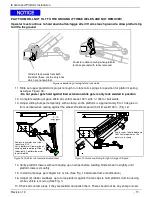
5. Verify that the 2 factory tack welds on each side at the lower knuckles are secure.
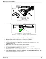
6. Set mount plates in place and tack weld using 3 fillet welds - 2” long on each side of mount plate and
on top of mount plate. Make sure to connect BODY LONG RAIL to mount plate, if necessary extend
mount plate with flat bar to reach BODY LONG RAIL. The mount plate should be flat on the channel.
7. Connect 2 Ga. battery cable to truck battery, aux battery or temporary battery
(Ref. 7 Electrical Installation)
8. Turn on On/Off switch. Completely cycle gate to assure proper alignment and functions
9. If it works remove factory tack welds from lower lift cylinder knuckle (Fig. 12)
10. Check if wires and hoses are not in the liftgate operational areas during moving at the platform.
Min. 8" Weld Overlap
1/4"
Use second jack to level
Underride Guard(ILFS)/
Rollover Wheel(ILP)
12 volt power may need to be
connected to release
pressure from Lift Cylinders
(Down Function)
Figure 13: Lift table and jack support


