


ILK
22/33/44/55/66
I
NSTALLATION
M
ANUAL
Revision 1.6
- 42 -
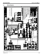
6.7
Hydraulic Schematic
Functions:
Lift: M
Lower: S1+S2+S5
Tilt Up: M+S5
Tilt Down: S3+S4
Horiz. Open: M+S3+S4
Pressure Relief
2850 PSI
200 bar
Shift Valve S5
Restrictor Valve R5
Flow Divider
Functions:
S1 and S2 = Release Valve for lowering function
S3 and S4 = Release Valve for tilt down function
R1 and R2 = Flow Restrictor located inside hose adaptor on lift cylinder
R3 and R4 = Flow Restrictor located inside hose adaptor on tilt cylinder
S5 = Shift Valve is activated on tilt up and lowering function
R5 = Restrictor Valve located in power pack
Flow Divider is activated, when fluid is going back into the power pack
If Flow Divider is loose or hanging up the fluid is circulated back in to tank
Figure 5.7: Hydraulic schematic


