


IV
Conventions
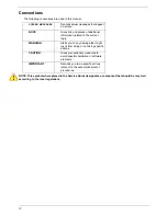
The following conventions are used in this manual:
NOTE: This symbol where placed in the Service Guide designates a component that should be recycled
according to the local regulations.
SCREEN MESSAGES
Denotes actual messages that appear
on screen.
NOTE
Gives bits and pieces of additional
information related to the current
topic.
WARNING
Alerts you to any damage that might
result from doing or not doing specific
actions.
CAUTION
Gives precautionary measures to
avoid possible hardware or software
problems.
IMPORTANT
Reminds you to do specific actions
relevant to the accomplishment of
procedures.
Содержание TM86 Series
Страница 6: ...VI ...
Страница 10: ...X Table of Contents ...
Страница 15: ...Chapter 1 5 System Block Diagram ...
Страница 62: ...52 Chapter 3 4 Remove one 1 screw from the 3G module 5 Lift the 3G card from the slot ...
Страница 73: ...Chapter 3 63 3 Disconnect the following four 4 cables from the Mainboard A B C D ...
Страница 78: ...68 Chapter 3 5 Lift the Right Speaker Module clear of the upper cover ...
Страница 83: ...Chapter 3 73 5 Lift the card reader board clear of the device ...
Страница 85: ...Chapter 3 75 5 Lift the USB board clear of the device ...
Страница 92: ...82 Chapter 3 5 Carefully lift the Thermal Module clear of the Mainboard ...
Страница 101: ...Chapter 3 91 5 Turn the board over and disconnect the cable ...
Страница 103: ...Chapter 3 93 4 Lift the LCD Panel clear of the module ...
Страница 105: ...Chapter 3 95 5 Disconnect the LVDS cable from the panel ...
Страница 107: ...Chapter 3 97 5 Lift the microphone set clear of the panel ...
Страница 114: ...104 Chapter 3 4 Replace six 6 securing screws three on each side of the LCD Panel brackets ...
Страница 117: ...Chapter 3 107 Replacing the Camera Module 1 Place the Camera in the module 2 Connect the camera cable ...
Страница 126: ...116 Chapter 3 6 Connect the LVDS cable and lock the connector 7 Connect the microphone cable ...
Страница 131: ...Chapter 3 121 4 Replace the FFC and press down as indicated to secure it to the Upper Cover ...
Страница 136: ...126 Chapter 3 3 Connect the following cables to the Mainboard 4 Connect D as shown 5 Connect C as shown A B C D ...
Страница 143: ...Chapter 3 133 4 Line up the right edge of the 3G cover and replace 5 Secure one 1 screw on the 3G Cover ...
Страница 187: ...Chapter 6 177 ...
Страница 188: ...Appendix A 178 Model Definition and Configuration Appendix A ...
Страница 212: ...202 Appendix C ...
Страница 215: ...205 BIOS 23 32 W Windows 2000 Environment Test 188 Wireless Function Failure 150 WLAN Module Removing 54 Replacing 130 ...
Страница 216: ...206 ...