


102
Chapter 3
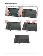
Replacing the Microphone Cable
1.
Place the microphone set in the panel.
2.
Fold the foil tab over to secure.
3.
Fold over the foil tabs and continue running the
microphone cable along the cable channel
indicated between the red callouts.
4.
Run the cable bundle along the hinge channel.
IMPORTANT:
Ensure that the LCD cable runs between the callouts to avoid trapping when the panel is replaced
in the LCD Module.
Содержание TM86 Series
Страница 6: ...VI ...
Страница 10: ...X Table of Contents ...
Страница 15: ...Chapter 1 5 System Block Diagram ...
Страница 62: ...52 Chapter 3 4 Remove one 1 screw from the 3G module 5 Lift the 3G card from the slot ...
Страница 73: ...Chapter 3 63 3 Disconnect the following four 4 cables from the Mainboard A B C D ...
Страница 78: ...68 Chapter 3 5 Lift the Right Speaker Module clear of the upper cover ...
Страница 83: ...Chapter 3 73 5 Lift the card reader board clear of the device ...
Страница 85: ...Chapter 3 75 5 Lift the USB board clear of the device ...
Страница 92: ...82 Chapter 3 5 Carefully lift the Thermal Module clear of the Mainboard ...
Страница 101: ...Chapter 3 91 5 Turn the board over and disconnect the cable ...
Страница 103: ...Chapter 3 93 4 Lift the LCD Panel clear of the module ...
Страница 105: ...Chapter 3 95 5 Disconnect the LVDS cable from the panel ...
Страница 107: ...Chapter 3 97 5 Lift the microphone set clear of the panel ...
Страница 114: ...104 Chapter 3 4 Replace six 6 securing screws three on each side of the LCD Panel brackets ...
Страница 117: ...Chapter 3 107 Replacing the Camera Module 1 Place the Camera in the module 2 Connect the camera cable ...
Страница 126: ...116 Chapter 3 6 Connect the LVDS cable and lock the connector 7 Connect the microphone cable ...
Страница 131: ...Chapter 3 121 4 Replace the FFC and press down as indicated to secure it to the Upper Cover ...
Страница 136: ...126 Chapter 3 3 Connect the following cables to the Mainboard 4 Connect D as shown 5 Connect C as shown A B C D ...
Страница 143: ...Chapter 3 133 4 Line up the right edge of the 3G cover and replace 5 Secure one 1 screw on the 3G Cover ...
Страница 187: ...Chapter 6 177 ...
Страница 188: ...Appendix A 178 Model Definition and Configuration Appendix A ...
Страница 212: ...202 Appendix C ...
Страница 215: ...205 BIOS 23 32 W Windows 2000 Environment Test 188 Wireless Function Failure 150 WLAN Module Removing 54 Replacing 130 ...
Страница 216: ...206 ...