


Chapter 6
173
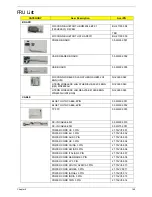
HEATSINK
THERMAL MOUDLE-UMA
60.WJ802.006
THERMAL MOUDLE-PARK
60.WJ702.001
THERMAL MOUDLE-MADISON
60.WJF02.001
SPEAKER
MIC SET
23.WJ802.001
SPEAKER R
23.WJ802.002
SPEAKER L
23.WJ802.003
MISCELLANEOUS
LCD SCREW PAD
47.WJ802.001
CPU/PROCESSOR
CPU INTEL CORE I5 520M 2.4G 3M
KC.52001.DMP
CPU INTEL CORE I5 430M PGA 2.26G ARD, UP TO
SC 2.53G, 3M L3
KC.43001.DMP
CPU INTEL CORE I3 330M PGA 2.13G 35W
ARRANDALE, TJ90, VT, 3M L3
KC.33001.DMP
LCD PANEL
LED LCD AUO 15.6"W WXGA GLARE B156XW02 V2
LF 200NIT 8MS 500:1 (POWER SAVING)
LK.15605.010
LED LCD LPL 15.6"W WXGA GLARE LP156WH2-
TLE1 LF 220NIT 8MS 400:1
LK.15608.002
LED LCD CMO 15.6"W WXGA GLARE N156B6-L0B
LF 220NIT 8MS 650:1
LK.1560D.010
LED LCD INNOLUX 15.6"W WXGA GLARE
BT156GW01 V2 LF 220NIT 8MS 600:1
LK.1560N.001
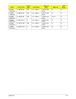
HDD/HARD DISK DRIVE
HDD HGST 2.5" 5400RPM 160GB
HTS545016B9A300 PANTHER B SATA LF F/W:C60F
DISK IMBALANCE CRITERIA = 0.014G-CM
KH.16007.026
HDD HGST 2.5" 5400RPM 250GB
HTS545025B9A300 PANTHER B SATA LF F/W:C60F
DISK IMBALANCE CRITERIA = 0.014G-CM
KH.25007.016
HDD HGST 2.5" 5400RPM 320GB
HTS545032B9A300 PANTHER B SATA LF F/W:C60F
DISK IMBALANCE CRITERIA = 0.014G-CM
KH.32007.008
CATEGORY
Acer Description
AcerPN
Содержание TM86 Series
Страница 6: ...VI ...
Страница 10: ...X Table of Contents ...
Страница 15: ...Chapter 1 5 System Block Diagram ...
Страница 62: ...52 Chapter 3 4 Remove one 1 screw from the 3G module 5 Lift the 3G card from the slot ...
Страница 73: ...Chapter 3 63 3 Disconnect the following four 4 cables from the Mainboard A B C D ...
Страница 78: ...68 Chapter 3 5 Lift the Right Speaker Module clear of the upper cover ...
Страница 83: ...Chapter 3 73 5 Lift the card reader board clear of the device ...
Страница 85: ...Chapter 3 75 5 Lift the USB board clear of the device ...
Страница 92: ...82 Chapter 3 5 Carefully lift the Thermal Module clear of the Mainboard ...
Страница 101: ...Chapter 3 91 5 Turn the board over and disconnect the cable ...
Страница 103: ...Chapter 3 93 4 Lift the LCD Panel clear of the module ...
Страница 105: ...Chapter 3 95 5 Disconnect the LVDS cable from the panel ...
Страница 107: ...Chapter 3 97 5 Lift the microphone set clear of the panel ...
Страница 114: ...104 Chapter 3 4 Replace six 6 securing screws three on each side of the LCD Panel brackets ...
Страница 117: ...Chapter 3 107 Replacing the Camera Module 1 Place the Camera in the module 2 Connect the camera cable ...
Страница 126: ...116 Chapter 3 6 Connect the LVDS cable and lock the connector 7 Connect the microphone cable ...
Страница 131: ...Chapter 3 121 4 Replace the FFC and press down as indicated to secure it to the Upper Cover ...
Страница 136: ...126 Chapter 3 3 Connect the following cables to the Mainboard 4 Connect D as shown 5 Connect C as shown A B C D ...
Страница 143: ...Chapter 3 133 4 Line up the right edge of the 3G cover and replace 5 Secure one 1 screw on the 3G Cover ...
Страница 187: ...Chapter 6 177 ...
Страница 188: ...Appendix A 178 Model Definition and Configuration Appendix A ...
Страница 212: ...202 Appendix C ...
Страница 215: ...205 BIOS 23 32 W Windows 2000 Environment Test 188 Wireless Function Failure 150 WLAN Module Removing 54 Replacing 130 ...
Страница 216: ...206 ...