


8
Chapter 1
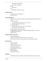
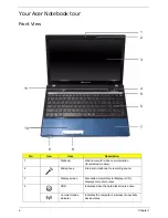
Left View
No.
Icon
Item
Description
1
DC-in jack
Connects to an AC adapter
2
Ventilation slots
Enable the computer to stay cool, even after
prolonged use.
3
External display
(VGA) port
Connects to a display device
(e.g. external monitor, LCD projector).
4
Ethernet (RJ-45)
port
Connects to an Ethernet 10/100-based
network.
5
HDMI
Connect to HDMI devices
6
USB 2.0 ports
Connect to USB 2.0 devices (e.g. USB mouse,
USB camera).
7
Microphone-in
jack
Accepts input from external microphones.
Headphones/
speaker/line-out
jack
Connects to audio line-out devices
(e.g. speakers, headphones).
1
4
3
5
6 7
2
Содержание TM86 Series
Страница 6: ...VI ...
Страница 10: ...X Table of Contents ...
Страница 15: ...Chapter 1 5 System Block Diagram ...
Страница 62: ...52 Chapter 3 4 Remove one 1 screw from the 3G module 5 Lift the 3G card from the slot ...
Страница 73: ...Chapter 3 63 3 Disconnect the following four 4 cables from the Mainboard A B C D ...
Страница 78: ...68 Chapter 3 5 Lift the Right Speaker Module clear of the upper cover ...
Страница 83: ...Chapter 3 73 5 Lift the card reader board clear of the device ...
Страница 85: ...Chapter 3 75 5 Lift the USB board clear of the device ...
Страница 92: ...82 Chapter 3 5 Carefully lift the Thermal Module clear of the Mainboard ...
Страница 101: ...Chapter 3 91 5 Turn the board over and disconnect the cable ...
Страница 103: ...Chapter 3 93 4 Lift the LCD Panel clear of the module ...
Страница 105: ...Chapter 3 95 5 Disconnect the LVDS cable from the panel ...
Страница 107: ...Chapter 3 97 5 Lift the microphone set clear of the panel ...
Страница 114: ...104 Chapter 3 4 Replace six 6 securing screws three on each side of the LCD Panel brackets ...
Страница 117: ...Chapter 3 107 Replacing the Camera Module 1 Place the Camera in the module 2 Connect the camera cable ...
Страница 126: ...116 Chapter 3 6 Connect the LVDS cable and lock the connector 7 Connect the microphone cable ...
Страница 131: ...Chapter 3 121 4 Replace the FFC and press down as indicated to secure it to the Upper Cover ...
Страница 136: ...126 Chapter 3 3 Connect the following cables to the Mainboard 4 Connect D as shown 5 Connect C as shown A B C D ...
Страница 143: ...Chapter 3 133 4 Line up the right edge of the 3G cover and replace 5 Secure one 1 screw on the 3G Cover ...
Страница 187: ...Chapter 6 177 ...
Страница 188: ...Appendix A 178 Model Definition and Configuration Appendix A ...
Страница 212: ...202 Appendix C ...
Страница 215: ...205 BIOS 23 32 W Windows 2000 Environment Test 188 Wireless Function Failure 150 WLAN Module Removing 54 Replacing 130 ...
Страница 216: ...206 ...