background image

Installation Instructions

The stove may be installed on a combustible floor provided ember protection made from a non-combustible material 
such as steel, ceramic tile, brick etc.is used. - This protection must extend as follows: 

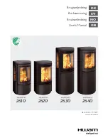
In Canada:  18" (457 mm) on the firing side and 8" (203 mm) to the other sides - See Figure 9. 

 Floor Protector 

In USA:  16" (406 mm) to the front and 8" (203 mm) to the sides of the fuel loading door opening - See Figure 10.  This protection is 
also required under the chimney connector and 2" (51 mm) beyond each side when using horizontal pipe.

8"  [203mm]

18"   [457mm]

8"  [203mm]

8"   [203mm]

Canada Only

Minimum Width - 43”(1.09m)

Minimum Overall Depth - 41”(1.04m)

Non-combustible 

floor protector

Figure 9:  Ember protector for Canada.

Figure 10:  Ember protector for USA.

 Combustion Air 

Intake or combustion air can be supplied to the stove in one of two ways.  Consult your local building code or CAN/CSA-B365, Installation Code for 
Solid-Fuel-Burning Appliances and Equipment before proceeding. The unit must have adequate air for combustion provided in the room the unit is 
installed in. 

1.  Outside air supply - 

(Necessary for mobile home installation, optional for residential installation.) Outside air may be drawn from either 

underneath the stove or from behind. 
 
Attach the intake starter to the bottom of the stove with the screws provided. 
 
To draw outside air through the floor, Cut or drill a 3-1/4"(83mm) diameter hole directly below the intake starter (on the bottom of the intake box). 
Connect intake starter through the floor with a 3" (102mm) inside diameter non-combustible tubing. . 
 
This hole must get its air from a ventilated crawl space or be extended with duct to the outdoors (See "Figure 12" on page 21). The use of 
outside combustion air for residential installation requires the unit to be secured to the structure to prevent dislodging of the air duct.   
 
To draw outside air from behind the stove, cut or drill a 3-1/4"(83mm) hole through the wall behind the unit. Use an appropriate household 3" 
(76mm) inlet. Connect the inlet to the intake starter section under the unit, with non-combustible tubing 

Note: 

This unit is not designed to be operated with the firing door open. In addition to the obvious hazard of sparks landing on combustibles, an open 

fire door will cause the heater to draw air from the living space and possibly cause suffocation. 

2.  Room air supply - 

Remove the cover plate or knockout from the bottom of the Intake box. The stove will now draw its air from the room through 

this opening and into the firebox intake.

Note: 

The living space around the heater must be well ventilated with good air circulation. Anything that may cause a negative pressure can cause 

gases or fumes to be pulled into the living area.  During extremely cold weather, and especially when burning at very slow rates, the upper parts of the 
exposed chimney may ice up, partially blocking the flue gases. If blockage occurs, flue gases may enter living space.

Note: 

An outside air pipe shield is available to place in front of the pipe used to bring outside air into the unit. Instructions for installation are provided 

with the shield.(Part #

NE12.7875.34

)

8" 

16"   

8" 

U.S.A. Only

Minimum Width - 33-3/8"(848mm)

Minimum Overall Depth - 28-1/2"(725mm)

Non-combustible

floor protector

18

290816-24_ NEO 1.2

5055.600-A

Содержание NEO 1.2A SERIES

Страница 1: ...icials about restrictions and installation inspection requirements in your area IMPORTANT THESE INSTRUCTIONS ARE TO REMAIN WITH THE HOMEOWNER MODEL NEO 1 2 SERIES A SERIAL TESTED and LISTED to CAN ULC...

Страница 2: ...r Draft 7 Ash Removal 7 Disposal of Ashes 7 Maintenance Checks 8 Weekly 8 Monthly 8 When Cleaning the Chimney System 8 Blower 8 Baffle Removal 9 Troubleshooting 10 Warranty Information 11 LTD Lifetime...

Страница 3: ...STOVE OR HOME THIS WOOD HEATER NEEDS PERIODIC INSPECTION AND REPAIR FOR PROPER OPERATION CON SULT THE OWNER S MANUAL FOR FURTHER INFORMATION IT IS AGAINST FEDERAL REGULATIONS TO OPERATE THIS WOOD HEA...

Страница 4: ...s The result of excessive creosote buildup is a chimney fire Chimney fires are dangerous Chimney inside temperatures can exceed 2000 F 1100 C This causes much higher than normal temperatures in the ch...

Страница 5: ...ties Manure or animal remains Materials containing plastic Materials containing asbestos Construction or demolition debris Materials containing rubber including tires Paper products cardboard plywood...

Страница 6: ...e found by trial and error and should be noted for future burns 2 To refuel adjust air control to High position all the way to the left and give the fire time to brighten Open the door slowly this wil...

Страница 7: ...ing of the chimney Smoke leaking into the room through appliance and chimney connector joints indicates inadequate draft Ash Removal Caution Ashes are to be removed only when the heater is cold Whenev...

Страница 8: ...ts heat value This is why hardwoods are generally preferred Green or wet wood will cause a rapid buildup of creosote If you feel it is necessary to burn wet or unseasoned wood do so only with the air...

Страница 9: ...ter installation clearances or within the space required for fuel loading and ash removal Keep the area around the heater clean and free of loose combustibles furniture newspapers etc 8 Establish a ro...

Страница 10: ...n 4 Door gasket leakage Replace gasket Check latch Excessive Creosote Buildup See 1 2 3 above Low Heat Output 1 Wood is wet Use dry wood 2 Fire too small Build a larger fire 3 Draft too low Chimney pl...

Страница 11: ...fect shall be repaired replaced or refunded at Pacific Energy s option The defective part may be required to be returned to Pacific Energy or an accredited agent transportation prepaid Porcelain is wa...

Страница 12: ...top and supports 2 Remove plastic cover 3 Using a 7 16 12mm wrench remove lag bolts that secure hold down brackets to bottom pallet Figure 2 4 Slide the hold down brackets away from the stove 31 3 4...

Страница 13: ...nel bracket Panel edge fits over top of the panel bracket Figure 5 5 Insert two screws into the back of the panel but do not tighten 6 Push panel from the front toward the rear so that there is no pla...

Страница 14: ...y and Connector Connect to a listed chimney or a chimney suitable for use with solid fuel that is lined and in good condition and meets local building codes The chimney flue size should be the same as...

Страница 15: ...the roof support 4 To start installing smoke pipe chimney connector slip crimped edge of the pipe inside the stove collar Use holes provided in collar to secure pipe with three screws 5 Install the re...

Страница 16: ...transportation of the mobile home Clearances This heater must be installed with a listed double wall connector and compatible chimney system Clearances to combustible surfaces and materials are shown...

Страница 17: ...4 Cut a hole in the ceiling and roof to suit the chimney system and frame in the sides The chimney support is mounted to the framing 5 If the chimney connector exits the mobile home less then 7 feet a...

Страница 18: ...diameter non combustible tubing This hole must get its air from a ventilated crawl space or be extended with duct to the outdoors See Figure 12 on page 21 The use of outside combustion air for residen...

Страница 19: ...L and H low and high operate blower speed control at desired setting Automatic To operate the blower automatically set the rocker switch on the side of the fan housing to Auto and set the speed contro...

Страница 20: ...2m Minimum Minimum 7 2 1m Ceiling Height 48 1219 mm Unit may be harder to start Please provide as much vertical length for the first section of pipe as possible The chimney may incorporate an offset T...

Страница 21: ...pace is well ventilated it is not necessary to extend air inlet to outside Ensure that the Masonry chimney meets all National Fire Protection Association and local building codes Have the chimney clea...

Страница 22: ...contains 6 full size firebricks as well as 6 various cut size bricks With the heater in the upright position install firebricks as follows Place 4 full size firebricks at the back of the heater first...

Страница 23: ...NEODGKIT 12 Baffle Assembly PERP787520 A 13 Brick rail set PERP787516 A 14 Brick rail shield PERP787533 A Replacement Parts NEO 1 2 WHEN ORDERING INCLUDE PART NUMBER WITH DESCRIPTION ITEM DESCRIPTION...

Страница 24: ...support please contact your retailer Web site http www pacificenergy net Printed in Canada 2016 Copyright Pacific Energy Fireplace Products LTD Reproduction adaptation or translation without prior wri...

Отзывы: