


Section 9
Routing
9-3
12/11
Wires Crossing other Components
Electrical wires crossing over other components, such as lines, bolt heads, fittings, engine components lifting eyes, engine
block, cylinder head, etc., close enough to rub shall be isolated with a covering of convoluted tubing
and
separated from
the component by using butterfly clamps, butterfly ties, or plastic sheathing. 110/220 volt engine heater wiring shall be
installed with butterfly ties or butterfly clamps.
Piping
Use no street elbows in air brake, water, fuel, or hydraulic systems unless specified on the piping diagram and the build
instructions .
Use no elbows in the air brake system unless specified on the air piping diagram and the build instructions.
Hoses Crossing Components
Hoses crossing over other components close enough to rub shall be protected with a secured covering of convoluted plas
-
tic tubing (KW part number K344-813), another section of hose, or plastic sheathing (KW part number K213-1312) . The
usage of butterfly ties, or butterfly clamps are also recommended.
Air Compressor Discharge Hoses
Wires or hoses shall not be tied to the high temperature air compressor discharge hose . Hoses and wires may be routed
across the air compressor discharge hose at a distance of 18 inches (457 mm) or greater from the compressor discharge
port. In this case the crossing hoses and wires shall be “butterfly” clamped to the air compressor discharge hose and cov
-
ered with convoluted tubing at the clamp point (use high temperature clamps on the compressor hose).
Bundles
HD mount and tie strap, or clamp shall be located at intervals not to exceed 14 inches (356 mm) along the bundle.
Regular tie straps shall be located at intervals not to exceed 7 inches (178 mm) between HD mount or clamps. Extra tie
straps may be used as needed to contain the hoses and wires in the bundle .
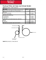
Routing of Wires and Hoses near Moving Components
Wires and Hoses shall be routed away from moving components, such as fans, shackle links, drivelines, steering linkages,
etc . so that there is at least 0 .5 inches (12 .7 mm) clearance when the component is operating at its
maximum
travel limits.
A minimum clearance of 1 .0 inchs (25 .4) shall be maintained between steering axle tires (and associated rotating parts) in
all positions and routed components, such as hoses, oil lines, wires, pipes, etc .
Содержание Kenworth T170 2011
Страница 1: ...Kenworth T170 T270 T370 and Hybrid 2011 Body Builders Manual...
Страница 2: ......
Страница 10: ...12 11 Section 1 Introduction Page Intentionally Left Blank...
Страница 52: ...Section 3 Dimensions 3 34 12 11 Automatic Transmission Allison 3000RDS...
Страница 53: ...3 35 Section 3 Dimensions 12 11 Manual Transmission...
Страница 111: ...Section 5 Frame Layouts 5 40 12 11 Page Intentionally Left Blank...
Страница 120: ...Section 6 Body Mounting 6 9 12 11 Page Intentionally Left Blank...
Страница 128: ...Section 7 Frame Modifications 7 8 12 11 Page Intentionally Left Blank...
Страница 137: ...Section 8 Electrical 8 9 12 11 FIGURE 8 10 Fuel Filter Restriction Pressure Gauge Sensor Location typical...
Страница 165: ...Section 8 Electrical 8 37 12 11 FIGURE 8 31 Cab Load Center mPDC...
Страница 170: ...Section 8 Electrical 8 42 12 11 Page Intentionally Left Blank...
Страница 179: ...12 11 Kenworth Truck Company P O Box 1000 Kirkland WA 98083 425 828 5000...


