


Section 8
Electrical
8-4
12/11
Functional Description
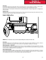
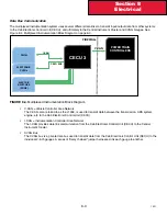
Cab Electronic Control Unit (CECU)
The heart of the multiplexed instrumentation system is the Cab Electronic Control Unit (CECU) . The CECU is located
behind the center console . See Figure 8-5 .
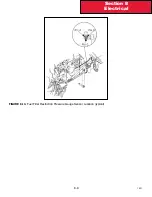
FIGURE 8-5.
CECU Location .
Vehicle component inputs are sent to the CECU through the J1939 data bus or conventional wiring. The CECU interprets
the various inputs and monitors/controls the functions for each input through the CECU software. Output signals from the
CECU provide data for the gauges, warning lamps, audible alarms, and displays inside the cluster.
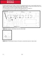
Central Instrument Panel
The central instrument panel includes the speedometer (including odometer and trip meter) and tachometer (including
engine hour meter and outside temperature display), plus a Driver Warning and Indicator Module (DWIM) pre-installed
standard and/or editable warning light symbols called “telltale” cards .
Each “telltale” card slides into the left and right sides of the Driver Warning and Indicator Module (DWIM) from the bottom.
The standard cards cover most warning light requirements; editable cards can be used for less common components that
also require warning lights .
The central instrument cluster receives input data from the CECU via the “I-CAN” (see Figure 8-3) data bus. When the
ignition key is first turned ON, the cluster will perform a calibration “power on self-test”.
Power On Self-Test
•
Ignition key turned ON
•
The speedometer and tachometer gauge pointers move from pointing at zero, counter-clockwise to their
mechanical limit (approx. -8°), stay there for one second and go back to pointing at zero
•
At the same time, all LED indicators and telltales are switched on together, except for position 4 and 11
•
A “Warning” sound sequence is also activated five times without break
CECU
Содержание Kenworth T170 2011
Страница 1: ...Kenworth T170 T270 T370 and Hybrid 2011 Body Builders Manual...
Страница 2: ......
Страница 10: ...12 11 Section 1 Introduction Page Intentionally Left Blank...
Страница 52: ...Section 3 Dimensions 3 34 12 11 Automatic Transmission Allison 3000RDS...
Страница 53: ...3 35 Section 3 Dimensions 12 11 Manual Transmission...
Страница 111: ...Section 5 Frame Layouts 5 40 12 11 Page Intentionally Left Blank...
Страница 120: ...Section 6 Body Mounting 6 9 12 11 Page Intentionally Left Blank...
Страница 128: ...Section 7 Frame Modifications 7 8 12 11 Page Intentionally Left Blank...
Страница 137: ...Section 8 Electrical 8 9 12 11 FIGURE 8 10 Fuel Filter Restriction Pressure Gauge Sensor Location typical...
Страница 165: ...Section 8 Electrical 8 37 12 11 FIGURE 8 31 Cab Load Center mPDC...
Страница 170: ...Section 8 Electrical 8 42 12 11 Page Intentionally Left Blank...
Страница 179: ...12 11 Kenworth Truck Company P O Box 1000 Kirkland WA 98083 425 828 5000...


