


Section 7
Frame Modifications
7-4
12//11
Do not drill new holes any closer than 2 inches (50 mm) to existing holes. Frame drilling
affects the strength of the rails and if not done properly can cause the frame rails to fail
and cause an accident.
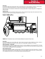
Before the rear suspension is relocated, check the new location of the spring hanger brackets . The new holes for the spring
hanger brackets must not overlap existing holes and should not come any closer than 2 inches (50 mm) to existing holes.
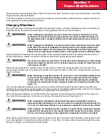
Original Wheelbase
Extended Wheelbase
Shortened Wheelbase
Cut Frame at Rear to
Obtain Desired Cutoff
Do Not Mount the
Suspension Bracket
On the Added
Frame Rail
Mount the suspension Brackets On the
Original Rail (see frame insert section &
figures 7-1 & 7-2)
Relocated Rear
Suspension
FIGURE 7-3.
Comparison of Original, Shortened, and Extended Wheelbases
Crossmembers
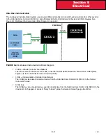
After changing a wheelbase, an additional crossmember may be required to maintain the original frame strength .
The maximum allowable distance between adjacent crossmembers is 60 inches (1524 mm) . If the distance between
adjacent crossmembers exceeds this dimension, add a crossmember between them . See Figure 7–4 .
Before Wheelbase is Lengthened
Less Than 60”
Greater Than 60”
Additional Crossmember
FIGURE 7- 4.
Crossmember Added when Distance Exceeds 60 inches (1524 mm)
WARNING:
Содержание Kenworth T170 2011
Страница 1: ...Kenworth T170 T270 T370 and Hybrid 2011 Body Builders Manual...
Страница 2: ......
Страница 10: ...12 11 Section 1 Introduction Page Intentionally Left Blank...
Страница 52: ...Section 3 Dimensions 3 34 12 11 Automatic Transmission Allison 3000RDS...
Страница 53: ...3 35 Section 3 Dimensions 12 11 Manual Transmission...
Страница 111: ...Section 5 Frame Layouts 5 40 12 11 Page Intentionally Left Blank...
Страница 120: ...Section 6 Body Mounting 6 9 12 11 Page Intentionally Left Blank...
Страница 128: ...Section 7 Frame Modifications 7 8 12 11 Page Intentionally Left Blank...
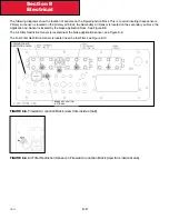
Страница 137: ...Section 8 Electrical 8 9 12 11 FIGURE 8 10 Fuel Filter Restriction Pressure Gauge Sensor Location typical...
Страница 165: ...Section 8 Electrical 8 37 12 11 FIGURE 8 31 Cab Load Center mPDC...
Страница 170: ...Section 8 Electrical 8 42 12 11 Page Intentionally Left Blank...
Страница 179: ...12 11 Kenworth Truck Company P O Box 1000 Kirkland WA 98083 425 828 5000...


