


Section 8
Electrical
8-8
12/11
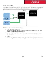
The following diagrams show the location of sensors on the firewall junction block. This is to aid in locating these sensors.
Primary Air sensor is located on the primary air block, the Secondary Air Sensor is located on the secondary air block, the
Application Air Sensor is located by the brake application block . See Figure 8-8 .
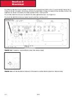
The Air Filter Restriction Sensor is located near the brake application sensor, see Figure 8-9 .
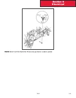
The Fuel Filter Restriction Sensor is located near the fuel filter, see Figure 8-10.
FIGURE 8-8.
Firewall Air Junction Block (view from inside of cab)
FIGURE 8-9.
Air Filter Restriction Sensor on Firewall Air Junction Block (view from inside of cab)
BRAKE APPLICATION
(OPTIONAL)
OPENING FOR AIR
RESTRICTION FILTER
Содержание Kenworth T170 2011
Страница 1: ...Kenworth T170 T270 T370 and Hybrid 2011 Body Builders Manual...
Страница 2: ......
Страница 10: ...12 11 Section 1 Introduction Page Intentionally Left Blank...
Страница 52: ...Section 3 Dimensions 3 34 12 11 Automatic Transmission Allison 3000RDS...
Страница 53: ...3 35 Section 3 Dimensions 12 11 Manual Transmission...
Страница 111: ...Section 5 Frame Layouts 5 40 12 11 Page Intentionally Left Blank...
Страница 120: ...Section 6 Body Mounting 6 9 12 11 Page Intentionally Left Blank...
Страница 128: ...Section 7 Frame Modifications 7 8 12 11 Page Intentionally Left Blank...
Страница 137: ...Section 8 Electrical 8 9 12 11 FIGURE 8 10 Fuel Filter Restriction Pressure Gauge Sensor Location typical...
Страница 165: ...Section 8 Electrical 8 37 12 11 FIGURE 8 31 Cab Load Center mPDC...
Страница 170: ...Section 8 Electrical 8 42 12 11 Page Intentionally Left Blank...
Страница 179: ...12 11 Kenworth Truck Company P O Box 1000 Kirkland WA 98083 425 828 5000...


