SET-UP AND ADJUSTMENTS
Unpacking
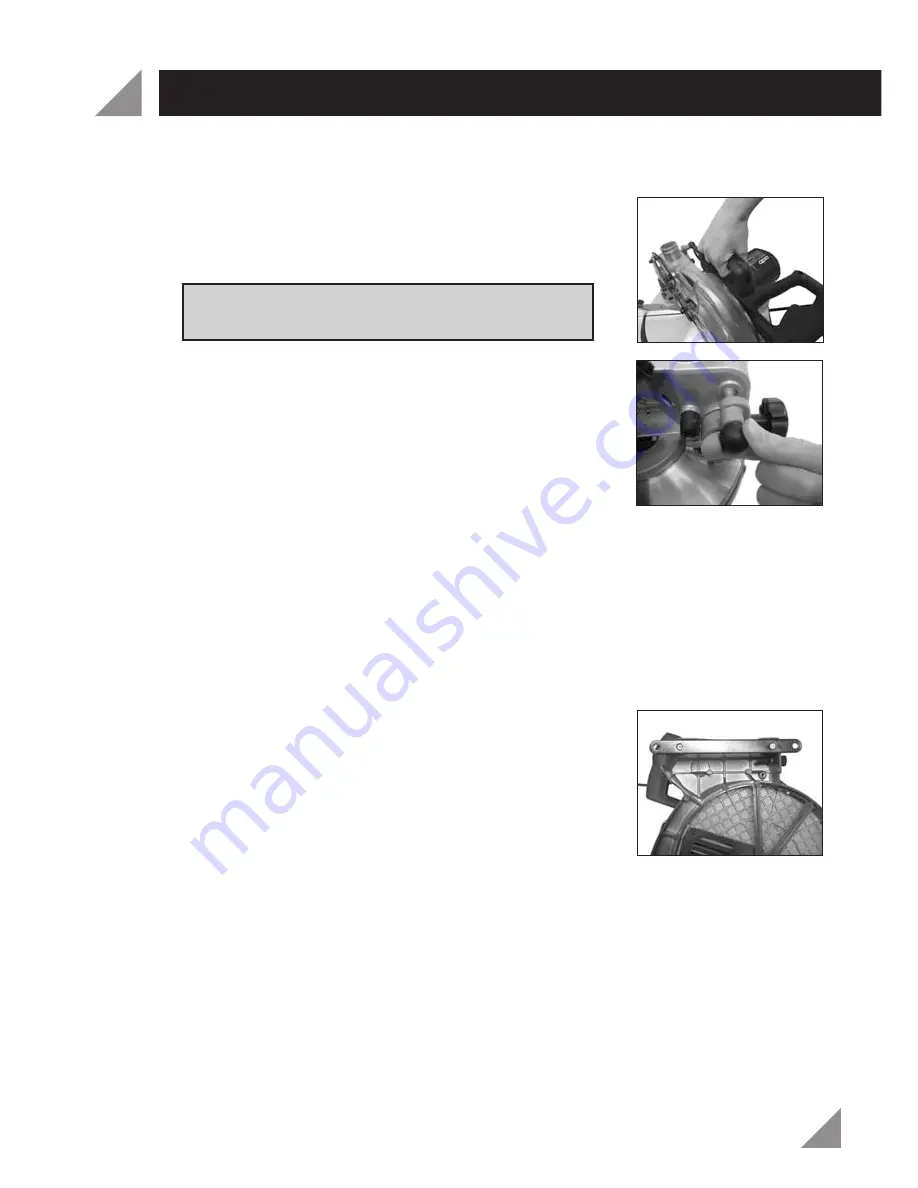
1. Remove the packaging materials from around the Mitre Saw and remove all parts
from the packaging.
2. Using the carry handle (6), carefully lift the Mitre Saw
from the packaging and place it on a level work
surface (Fig. 1).
Warning!
Do not lift the Mitre Saw whilst holding
on to the guards. Use the carry handle (6).
3. The Mitre Saw has been shipped with the cutting head
(4) in the locked down position. To release the cutting
head (4), push down on the operating handle (7), pull
the head locking pin (5) (Fig. 2) and gently raise the
cutting head (4).
Transportation
Ensure the Mitre Saw is turned off and disconnected from the power source before
transporting. Lift the Mitre Saw only when the cutting head (4) is in the locked down
position. Only lift the Mitre Saw by the carry handle (6) or outer castings. Do not lift
the Mitre Saw using the retractable safety guard (9) or the operating handle (7).
Bench Mounting
1. Gently turn the mitre saw on its side.
2. Align the two holes in the work bench mounting rails
(28) with the two rubber feet on the base (18) of the
mitre saw. Ensure the counter-sunk holes in the
mounting rails are facing away from the saw (Fig. 3).
3. Use the four screws (31) provided to secure the work
bench mounting rails (28) to the base (18) of the mitre
saw (Fig. 3). Each screw can be pushed through the
rubber foot and secured to the base (18) using a
Phillips head screwdriver.
4. Mount the Mitre saw onto a workbench or mitre saw stand using the work bench
mounting rails (28) fixed to the mitre saw. Ensure the surface is level and balanced.
5. Use four bolts and nuts (not included) to secure the Mitre Saw to the workbench or
mitre saw stand.
Releasing the Head Locking Pin
The head locking pin (5) is used to hold the cutting head (4) down when transporting
or storing the Mitre Saw. The Mitre Saw must not be used when it is in lockdown position.
1. To release the cutting head (4) push down on the operating handle (7) pull the
head locking pin (5) (Fig. 2) and let go, gently raise the cutting head (4).
Fig. 1
Fig. 2
Fig. 3
8


