


Installation
t
2-23
C
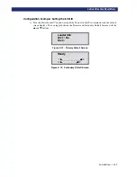
ONFIGURATION
O
PTIONS
D
ESCRIPTION
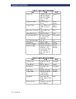
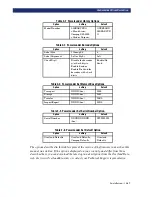
Drive n Bus ID:
Allows you to set the SCSI addresses of the drives. The designators Drive 1
through Drive n refer to the first through nth drives, counting from the top module in the
PowerLoader™.
Vendor ID:
Allows you to specify the response of the LibraryPro™'s robotics to the SCSI
Inquiry command in the Vendor ID field. The default is OVERLAND.
Product ID:
Allows you to specify the response of the LibraryPro™'s robotics to the SCSI
Inquiry command in the Product ID fields (LIBRARYPRO, LXB, EXB-210, EXB-440, EXB-480,
SSL2000 Series C, <Vendor unique>. The default is LIBRARYPRO.
Negotiation Mode:
Allows you to enable Initiate Synchronous Negotiation. Initiate
Synchronous Negotiation, if set, allows the LibraryPro™ to initiate SCSI Synchronous
Negotiation with the host (the default is No). The LibraryPro™ always responds to host-
initiated synchronous negotiation.
Transfer Rate:
Allows you to set the data Transfer Rate to 10 MB/sec, 5 MB/sec or
Asynchronous. The default is 10 MB/sec.
Mode Page 1F Length:
Allows you to choose between two lengths of the Mode Sense/Select
Device Capabilities Page (SCSI Page 1Fh), which are Short (14 bytes) and Long (18 bytes), to
accommodate different SCSI device implementations of this page. The default is Short.
Abort Move Status:
Enables you to specify the module’s response if it receives a SCSI Reset or
Abort while a Move Medium command is in progress. Depending on this setting, during
execution of the Move Medium command, the module will return either Busy or Not ready in
response to the SCSI Reset or Abort. The default is Busy.
Initialize Element Status:
Allows you to specify the module's response to the SCSI Initialize
Element Status command. The possible settings are No Inventory, Force Inventory, and Force
Label Scan. The default is No Inventory.
Unit Attn Report:
Allows you to select reporting of All or only One unit attention conditions. If
set to All, the unit reports all unit attention conditions in sequence; if set to One, the unit
reports only the highest priority condition. The default is All.
SCSI Mode:
Defines the loader as SCSI-2 or SCSI-3. The default is SCSI-2.
Post Recv'd Error:
Enables reporting of TapeAlert informational exception conditions with a
Recovered Error sense key, when the Method of Reporting Information Exceptions (MRIE) field
is set to a value of 0x3 in Mode Page 1Ch, or if the TapeAlert Mode option is set to Rec Error
(cnd). The default is Disabled.
Tape Alert Mode:
Specifies conditions for logging and reporting TapeAlert data. The default
is Logging Disabled.
•
Logging Disabled-Inhibits logging feature.
•
No Exceptions-Device should not report information exceptions.
•
Unit Attention-Report information exceptions with a Unit Attention sense key and an
ASC/ASCQ of 5D/00.
•
Rec Error (cnd)-Report information exceptions with a Recovered Error sense key and an
ASC/ASCQ of 5D/00, if Recovered Error Reporting is enabled.
Содержание PowerLoaders AIT-2
Страница 1: ......
Страница 4: ...ii u...
Страница 13: ...xi LIST OF FIGURES CONT D...
Страница 14: ...xii LIST OF FIGURES CONT D...
Страница 16: ...xiv LIST OF TABLES CONT D...
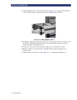
Страница 26: ...2 2 u Installation RELEASING THE LOCKDOWN MECHANISM Lockdown Screw...
Страница 52: ...2 28 u Installation CONFIGURATION OPTIONS DESCRIPTION...
Страница 96: ...5 18 u Troubleshooting ERROR RECOVERY...
Страница 102: ...A 6 u Specifications SPECIFICATIONS...
Страница 104: ...B 2 u...


