background image

40

Chapter 2 - Installation

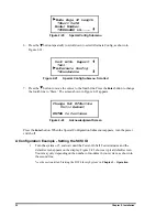
Figure 2-30

Set Reserved Slots Submenu

3. With 

the   next to line 1, press the 

Enter

 button The   moves to line 2, a  

appears at the end of line 4, and a   appears at the end of line 1. Now you can use
the   and   buttons to scroll line 2 to specify the number of slots to be reserved.
Scroll to the desired number, then press the 

Enter

 button to save the new selection.

The screen displays a message to remind you that your selection does not take effect
until you reboot the system. You can reboot by cycling power off, then on.

4. Press 

the 

Escape

 button repeatedly to return to the Default Screen.

Descriptions of Configuration Options

The items available on the Configuration Menu are as follows:

Set Data Format: This setting enables you to 1) set the data format to Auto Selection,
THZ01, THZ02, DLT2000, DLT2000XT, DLT4000; or DLT7000; and 2) enable or disable
data compression. Compression can not be enabled when either THZ01 or THZ02 format is
in use. This setting applies to the next or the currently loaded cartridge only. An unload
command returns to the default. This setting does not display the current format of the loaded
tape. Use the Show Status Menu for this purpose. The defaults are Auto Selection and
compression Disabled.

Set SCSI: This setting enables you to 1) enable or disable the library robotics SCSI bus
parity checking, and 2) set the SCSI addresses of the drives and the library robotics. The
defaults are: parity enabled; Library Bus ID = 6. The designators DLT 1 through DLTn refer
to the first through nth drives, counting from top to bottom. The actual designator used by the
system depends on the number of drives in the system and the placement of the module in the
system;

Set Element Base: This setting allows you to set the base addresses of each of the four SCSI
elements of the module. In order to identify sources and destinations in commands to the
robotics, the Library System is divided into elements, each of which is assigned a separate
designator or element address. The Transport Element is the robotics mechanism itself; the
Storage Elements are the slots in the magazines; the Transfer Elements are the drives, and the
Import/Export Element is the mail slot or slots. The Module reports these settings in response
to the SCSI Mode Sense command, in the Element Address Assignment Page. The defaults
are Transport element base = 0000; Storage element base = 0001, Transfer element base =
00F0, and Import/Export element base = 00E0.
Set Identification: This setting enables you to specify the response of the Module’s robotics
to the SCSI Inquiry command in the Vendor ID and the Product ID fields. The defaults are:
Vendor ID = OVERLAND; Product ID = LXB.

Set Date: Enables you to set the system’s calendar.

Set Time: Enables you to set the system’s clock.

Reserved Slots:

  *0

Содержание DLT LibraryXpress Series

Страница 1: ...104140 101 Revision A 7 97 LibraryXpress Series DLT Library System Including LXG LXB and LXC Modules and XpressChannel Service Manual DIGITAL Part Number EK TL890 SV A01...

Страница 2: ...These changes will be incorporated in new editions of this publication Overland Data assumes no responsibility for the accuracy completeness sufficiency or usefulness of this manual nor for any probl...

Страница 3: ...der 9 ADVANCED DESIGN FEATURES 9 Embedded Diagnostics 10 Error Checking 10 Buffer 10 Compression 10 Capacity 10 Media Life 11 RELATED PUBLICATIONS 11 CHAPTER 2 INSTALLATION 13 INTRODUCTION 13 PLANNING...

Страница 4: ...REMOVING CARTRIDGES 63 Removing a Magazine 64 Emergency Magazine Removal 65 Inserting Cartridges Into the Magazine 65 Inserting a Magazine 65 BASE MODULE 67 CAPACITY MODULE 68 TAPE REQUIREMENTS 68 Ca...

Страница 5: ...IONS 133 INDEX 135 Figures FIGURE 1 1 GLOBAL CONTROL MODULE FRONT VIEW 5 FIGURE 1 2 BASE MODULE FRONT VIEW 6 FIGURE 1 3 CAPACITY MODULE FRONT VIEW 6 FIGURE 1 4 BASE MODULE 10 CARTRIDGE MAGAZINE 7 FIGU...

Страница 6: ...LT SCREEN 50 FIGURE 3 9 LIBRARYXPRESS MENU STRUCTURE 52 FIGURE 3 10 MAIN MENU 53 FIGURE 3 11 PANEL LOCKED SCREEN 53 FIGURE 3 12 CODE ENTRY SUBMENU 53 FIGURE 3 13 SHOW STATUS MENU 54 FIGURE 3 14 LIBRAR...

Страница 7: ...6 CONTROL PANEL 95 FIGURE 6 7 CONTROLLER PWB CONNECTOR LOCATIONS 96 FIGURE 6 8 CONTROLLER PWB CONNECTOR LOCATIONS EARLY BASE MODULE 97 FIGURE 6 9 DOOR OPENER MAGAZINE LOCK ASSEMBLY 100 FIGURE 6 10 FAN...

Страница 8: ......

Страница 9: ...nel In a DLT LibraryXpress System you can combine modules to provide the right combination of capacity and performance to meet your present requirements Overland Data s SmartScale Storage architecture...

Страница 10: ...many drives it is desirable to use multiple SCSI busses for the drives so the data transfer rate of the drives is not limited by bus bandwidth In a large high performance system drives may be connect...

Страница 11: ...dels can also read and write DLTtape III cartridges Both read and write densities are selectable from the front panel and under SCSI control from the host Note It is strongly recommended that if you d...

Страница 12: ...or those applications requiring that some combination of drives and robotics be daisy chained to a single SCSI bus These configurations are described in more detail in the section on SCSI Interfaces i...

Страница 13: ...high performance library robotics system Conversion of Free Standing Base Modules for System Use Your existing LibraryXpress Base Modules may be added to your system by resetting internal jumpers rem...

Страница 14: ...panel features a 4 line by 20 character backlit LCD display three or four LED indicators and four buttons The buttons enable the operator to navigate through the menu structure to select and display...

Страница 15: ...re 100 120 VAC and 200 240 VAC The power supply is capable of operating at 50 or 60 Hz without any adjustment or modification AC power is supplied to the power supply by a single IEC compatible socket...

Страница 16: ...8 Chapter 1 Introduction Figure 1 5 Global Control Module Rear View Figure 1 6 Base Module Rear View...

Страница 17: ...a s Mainframe Class Library Robotics which is known for ruggedness and reliability Bar Code Reader The optional bar code reader may be mounted on the cartridge shuttle in each module It reads bar code...

Страница 18: ...ply a 16 bit parity check to each record a 64 bit CRC to each 4 kB of data and Reed Solomon error correction code overall In addition there is an internal parity check on the data buffer Buffer Drives...

Страница 19: ...ile content The native capacity for a full Base Module magazine is ten times the native capacity per cartridge for Global Control and Capacity Modules 16 times the native capacity per cartridge Media...

Страница 20: ......

Страница 21: ...on options to your particular application The remainder of this chapter describes each of these steps Planning Your Installation The DLT LibraryXpress System is intended to be mounted in a standard 19...

Страница 22: ...nnected to LibraryXpress modules The Global Control Module senses the position of each module during initialization at power up Even if there are gaps between modules the system will operate correctly...

Страница 23: ...modules Follow the instructions for installing rack slides later in this chapter After the rack slides and the slave modules are in place and after the XpressChannel is assembled you will install the...

Страница 24: ...ith two captive screws Carefully note the orientation of the block with respect to the car as shown in Figure 2 3 Orientation of Parts During Assembly To determine the orientation of an extension sect...

Страница 25: ...ngth is correct for your system turn to the section titled Mounting the Module Rack Slides and continue on to the end of the chapter If you need to add sections please take a few minutes to read this...

Страница 26: ...Be sure that the beveled edge is toward the inside corner of the sections 6 Install two M3 x 20 mm Phillips sems screws through each tie bar into the threaded holes in the flanges of the extrusion se...

Страница 27: ...on the rear surface of that section Be sure that the word LEFT that is stamped on the brace is upright 11 Insert two M4 x 20 Phillips sems screws through the holes in the support brace into the holes...

Страница 28: ...the belt toward you position the right end of the belt about halfway along the XpressChannel 6 Referring to Figure 2 5 thread the left end of the belt counter clockwise around the motor drive pulley 7...

Страница 29: ...Chapter 2 Installation 21 Figure 2 6 Threading the Belt Through the Base Section Figure 2 7 Checking Belt Length...

Страница 30: ...ce between the ends of the belt approximately 1 32 10 Tighten the four screws that hold the belt retaining plates C a p ti ve Sc re w s Pre ss D o w n Figure 2 9 Aligning the Captive Screws With the B...

Страница 31: ...ding the two preceding sections To add to an existing XpressChannel you must first partly disassemble it then make the necessary changes as described in the preceding sections Use the following proced...

Страница 32: ...earance behind the rear panel of the module CAUTION Make certain that when the module is fully extended that a force of 20 of the rack weight but not more than 57 lb applied in any direction but upwar...

Страница 33: ...k Slide Parts 1 Refer to Figure 2 10 to identify and orient the parts of the slides The slide is attached to the Module enclosure by means of three screws through the inner slide These will be accessi...

Страница 34: ...Locate the screw holes in the front and rear rails of the cabinet or equipment rack where the module is to be installed 4 Assemble a mounting bracket to each outer slide using two 10 32 screws with w...

Страница 35: ...tive screws just begin to engage then tighten the captive screws to fully seat the module Note Do not slam the module against the rack Doing so can dislodge the clip nuts 16 Repeat this procedure for...

Страница 36: ...t module and c The XpressChannel is pressed firmly against the backs of the top and bottom modules 6 One by one push the remaining modules into place and tighten the captive screws In each case ensure...

Страница 37: ...tics that is located in the slave modules is controlled by the Global Control Module through a cable connected to the Global Control Interface connector on each module Each module has a separate AC po...

Страница 38: ...a Harmonized cord marked HAR or a nationally certified cord SCSI Interfaces DLT LibraryXpress Modules may be ordered with a choice of single ended or differential SCSI 2 interfaces or if 7000 series...

Страница 39: ...at the end of each bus as explained below in the section headed Interface Cable and Terminator Installation Figure 2 13 shows the SCSI cable connectors and bus terminator used on the module In order...

Страница 40: ...ce can be found in ANSI X3 131 1994 or later Note This equipment has been tested for electromagnetic emissions and immunity using good quality shielded cables The use of unshielded cables poor quality...

Страница 41: ...nnectors Terminator Jumpers and Cables SCSI 2 Interface Daisy chained Connection Shown To properly cable a module 1 Make sure that your host system has an appropriate SCSI interface card for each SCSI...

Страница 42: ...s The setting of each option is stored in non volatile memory in the module For most applications you will not need to change the factory default settings To change settings you need to use the Contro...

Страница 43: ...e 2 18 appears Figure 2 18 Configure Submenu 4 Press the button repeatedly to select Set Special Configuration as shown in Figure 2 19 Set Serial Number Set Unload Mode Set Negotiation Set Special Con...

Страница 44: ...ne to Slave The screen shown in Figure 2 22 appears Change Not Effective Until Reboot ENTER to Continue Figure 2 22 Acknowledgment Screen Press the Enter button When the Special Configuration Submenu...

Страница 45: ...ation options that can be reached by scrolling with the button Figure 2 25 Configure Submenu 4 To select a configuration option press the or button on the control panel until the on the display is nex...

Страница 46: ...on The moves to line 2 and the remains at the end of line 4 and a appears at the end of line 1 Now you can use the and buttons to scroll line 2 to display the possible settings Scroll downward so that...

Страница 47: ...to line 4 Now you can use the and buttons to scroll line 4 to specify how many slots will be designated as mail slots Scroll to the desired number then press the Enter button to save the new selection...

Страница 48: ...isable the library robotics SCSI bus parity checking and 2 set the SCSI addresses of the drives and the library robotics The defaults are parity enabled Library Bus ID 6 The designators DLT 1 through...

Страница 49: ...t It is implemented using SCSI Import Export elements Set Reserved Slots Some host software imposes size limits on tape library magazines for licensing purposes and will not operate with a library tha...

Страница 50: ...0 Auto Selection Compression Enabled Disabled Enabled at 10 0 only Auto Disabled SCSI Lib Bus Parity Enable Disable Lib Bus ID SCSI ID DLT1 Bus ID SCSI ID DLTn Bus ID SCSI ID Enabled 6 Element Base Tr...

Страница 51: ...gh n 0 Special Config Mode Page 1F Length Short 0x0E Long 0x12 Model Number OVERLAND LX Blank Line Vendor Unique Init Elem Status No Inventory Force Inventory Force Label Scan Unit Attn Report One All...

Страница 52: ......

Страница 53: ...ontrol module includes a power switch for the module and the control panel which has buttons a display and indicators Figure 3 1 shows the front panel Figure 3 1 Global Control Module Front Panel Powe...

Страница 54: ...el or from the host computer The Ready indicator goes out when you enter the Menu Mode The Alert LED yellow indicates that a fault or some other matter that requires attention has occurred in one of t...

Страница 55: ...s submenu When either the Drive Fault or the Loader Fault LED red is illuminated a Fault Screen appears on the LCD display The Fault Screen is described later in this chapter A list of fault symptom c...

Страница 56: ...cape button while the Main Menu is displayed exits the Menu Mode and returns you to the Default Screen The Default Screen is shown in Figure 3 6 the Main Menu is shown in Figure 3 10 3 To display the...

Страница 57: ...Errors N A N A Note 1 There is an auto repeat feature for the and buttons When the user presses either button for more than one half second the control panel behaves as if the user were pressing and...

Страница 58: ...a are described later in this chapter Starting the System Note When turning on power to the DLT LibraryXpress System power must be applied to the Global Control Module either simultaneously with or af...

Страница 59: ...nes represent the cartridge magazine in the Global Control Module A rectangle will appear in each position which contains a cartridge An underline represents an empty slot Fault Screen When a fault is...

Страница 60: ...the Base Module On line 4 a rectangle appears in each position which contains a cartridge An underline would appear at each empty slot The numbers at the beginning and end of line 4 represent the numb...

Страница 61: ...he module within the system and the size of the magazine If no magazine is installed line 4 says No Magazine The boxes which are present on this line indicate that a cartridge is present in the corres...

Страница 62: ...ng the Menu Mode Important Note When the Global Control Module enters the Menu Mode the Ready light goes out This means that the module is offline and responds to all commands from the host with a SCS...

Страница 63: ...10 Main Menu Note If the Control Panel has been locked the screen shown in Figure 3 11 appears instead of Figure 3 10 You must know the unlock code for the system before you can proceed Figure 3 11 P...

Страница 64: ...e submenu The at the end of the fourth line of the Main Menu means that there are one or more additional items that can be reached by scrolling using the button The items available on the Main Menu ar...

Страница 65: ...re Revision Date Time Loader Status Library Configuration Vendor Identification Product Identification Transport Address Storage Address Transfer Address Imp Exp Address Serial Number Wide SCSI SCSI B...

Страница 66: ...perate Handle Map Information Screen When you select Map Info the screen in Figure 3 16 appears The location being reported appears on Line 1 The content of the bar code on the label up to 8 character...

Страница 67: ...w History Menu The Show History Menu enables the operator to review the history of the system An example of the use of the Show History Menu appears later in this chapter under the heading Displaying...

Страница 68: ...our digits Be sure to remember the 4 digit number as you will need it in order to enter the Menu Mode An unlock code of 0000 disables panel locking When you have finished entering four digits press th...

Страница 69: ...e code is incorrect an error screen appears If you have forgotten your unlock code contact your technical support representative for assistance Displaying Firmware Revision You may display the library...

Страница 70: ...d buttons scroll the list to display the error history of the module Loading and Unloading Tapes The Load Unload menus enable you to specify a source and a destination for a cartridge movement As a re...

Страница 71: ...rolled the default selection offscreen and haven t yet selected an item from the list Note The contents of the lists on line 2 and line 4 will vary as follows Initial Screen From Line The list on line...

Страница 72: ...hoices because 1 you have selected a slot as the source so the destination must be a drive and 2 DLT2 already has a cartridge in it so it cannot be a valid destination Press the Enter button to select...

Страница 73: ...gure 3 31 When the Magazine Security Lock is locked the Unlock Open button has no effect If the module is installed in a reasonably secure environment you may elect to leave the Magazine Security Lock...

Страница 74: ...er button to display the Main Menu shown in Figure 3 32 Note if the display says that the front panel is locked you need to know the unlock code for your system See the section titled Entering the Men...

Страница 75: ...a fault occurs that prevents removal of the magazine turn the power off for five seconds Power up while continuously pressing the button Continue to hold the button until all of the indicators on the...

Страница 76: ...o display the Main Menu Note if the display says that the front panel is locked you need to know the unlock code for your system See the section titled Entering the Menu Mode earlier in this chapter f...

Страница 77: ...s 2 through 4 10 Press the button three times to move the next to Lock All Media then press the Enter button The display will appear as follows Figure 3 41 Lock All Media Screen 12 All media are now l...

Страница 78: ...indicator and the control panel shown in Figure 3 2 The Capacity Module has a 16 slot magazine and no tape drives Tape Requirements The LibraryXpress uses ECMA approved and ANSI proposed standards DLT...

Страница 79: ...e 3 43 DLTtape Cartridge Write Protection The write protection switch of a DLTtape cartridge is also shown in Figure 3 43 To enable data recording slide the write protect switch to the right so that n...

Страница 80: ......

Страница 81: ...ll a cleaning cartridge how to clean a drive and how to remove the cleaning cartridge The default location for a cleaning cartridge is slot 1 That is unless you specify a different slot when you start...

Страница 82: ...described in Chapter 3 Operation in the section titled Inserting and Removing Cartridges 3 Remove any cartridge present in Slot 1 the slot nearest the handle 4 Insert the cleaning cartridge into Slot...

Страница 83: ...2 Maintenance Menu 3 Press the Enter button once to select Clean Drive The following screen appears Figure 4 3 Cleaning Submenu 4 Lines 2 and 4 are scrollable The choices available on Line 2 are DLT1...

Страница 84: ...n unload each as described in Chapter 3 Operation in the section titled Loading and Unloading Tapes 2 Remove the magazine from the Global Control Module using the procedure described in Chapter 3 Oper...

Страница 85: ...used serial port on the PC and the Global Control port on the rear panel of the Global Control Module 2 If you are operating in windows exit from windows or open a DOS window 3 Insert the upgrade disk...

Страница 86: ...ck the following screen appears Flash Firmware Update Successful Please Wait While Library Reboots Figure 4 11 Flash Update Completion Screen The Global Control Module now reboots Do not turn the powe...

Страница 87: ...ion between the Global Control Module and one or more slave modules or between a module s processor and a drive processor or b a mechanical malfunction within the LibraryXpress System In most cases bo...

Страница 88: ...nt panel of the Global Control Module Table 5 1 Error Recovery Procedures ERP NUMBER PROCEDURE DETAIL C Cycle power to the drive using the AC switch on the front panel of the module Wait 30 seconds to...

Страница 89: ...ar C D G 3002 Picker Tach Errors Power Down to Clear D G 3003 Elevator Tach Errors Power Down to Clear D G 3004 Elevator Jammed Power Down to Clear C D G 3005 Picker Jammed Power Down to Clear C D G 5...

Страница 90: ...e Maintenance Menu The display will show something similar to the following Clean Drive Diagnostic Menu Demo Menu Flash Update Figure 5 3 Maintenance Submenu 3 Press the button once to move the next t...

Страница 91: ...ect Scanner Feedback the library robotics displays the output of the optical scanner if it is installed while releasing control of the shuttle motor so it is free to move You can manually move the shu...

Страница 92: ......

Страница 93: ...d below can be replaced in the field Part numbers are listed in Appendix B The operations described in this chapter are intended to be performed by qualified Customer Engineers If you do not have such...

Страница 94: ...octite 222 Important Note All screws that do not use lock washers captive washers or lock nuts must have Loctite 222 applied when reassembled in the field Neglecting this step may result in premature...

Страница 95: ...Chapter 6 Parts Removal and Replacement 87 Figure 6 1 Parts Locations Base Module Figure 6 2 Parts Locations Global Control and Capacity Modules...

Страница 96: ...ce cables at the rear of the module 3 Pull the module out of the rack on its slides until both slides lock in the extended position 4 Note This step should be performed by two people one on each side...

Страница 97: ...ediate slides for the removed module outward until they lock in the extended position 5 Note This step should be performed by two people one on each side of the module Lift the module from the work su...

Страница 98: ...on to release the magazine then pull it straight out by its handle Reasons Why It Might Not Work 1 The host computer has disabled the Unlock Open button using the SCSI Prevent Allow Medium Removal com...

Страница 99: ...nd three 3 8 holes on the top Refer to Figure 6 1 and Figure 6 9 4 Insert a straight bladed screwdriver through the center 3 8 hole to engage a slotted shaft about 1 1 2 below the bracket 5 Turn the s...

Страница 100: ...hat holds one or two DLT drives and their associated cabling It includes the SCSI interface connectors and cables for the Base Module the power cables for the drives and communications cables from the...

Страница 101: ...ent RS 422 cables 3 at the drives Remove the cables from under the cable clamps and lift them clear of the caddy 5 Remove two M4 x 8 mm flat head Phillips screws 4 along the upper edge of the Caddy As...

Страница 102: ...ect the Drive 1 and Drive 2 if present RS 422 cables 3 at the Controller PWB Refer to Figure 6 8 for connector locations 5 Connect the drive power cable 2 to the Power Supply connector 6 Connect the S...

Страница 103: ...ead Phillips sems screws one in each standoff that hold the Control Panel to the Front Panel Do not overtighten 3 At the Control Panel end plug in the cable that connects the Control Panel to the Cont...

Страница 104: ...used in some early production Base Modules Note that there is a vertical row of connectors near the front of the PWB a row near the top edge at the rear of the board a large SCSI connector along the...

Страница 105: ...odule the drive RS 422 connectors labeled Drive1 RS 422 and Drive2 RS 422 On a Global Control Module remove the trace connector cable 5 Slide the PWB out about one third of the way 6 Disconnect the 5...

Страница 106: ...s seated in the two guides on the bottom of the chassis 10 Connect the control panel cable and the 4 pin lock switch assembly cable near the front of the PWB 11 In the LXB and LXC connect the Global C...

Страница 107: ...sen or remove the screw near the center of the bracket 5 While holding the door open pull the door opener bracket toward the left side of the chassis Lift the door opener free of the chassis and set i...

Страница 108: ...rts are supplied as a factory adjusted matched pair Do not mix old and new parts 1 Locate the end of the motor cable While holding the motor bracket inside the electronics compartment connect the moto...

Страница 109: ...ll three M4 x 8 mm Phillips flat head screws along the straight edges of the door opener bracket Note Apply Loctite 222 to the threads of each screw before inserting Release the door 10 Replace the co...

Страница 110: ...ottom 2 Insert the fan power cable connector underneath the drive caddy platform and push on the cable until the connector emerges inside the electronics compartment 3 While holding the fan in place p...

Страница 111: ...ly Global Control and Capacity Modules Replacement Global Control and Capacity Modules Refer to Figure 6 11 1 Orient the fan and finger guard against the right side of the bulkhead so that the fan pow...

Страница 112: ...he left of the door is accessible 3 Remove the Power Supply Assembly as described in this chapter It is not necessary to disconnect the power switch or remove the grounding ring lug 4 Remove the Magaz...

Страница 113: ...front end While holding the front of the leadscrew with a 7 16 open end wrench over the flats turn the leadscrew retaining nut clockwise with an 11 mm open end wrench until it has moved about 1 4 inch...

Страница 114: ...s turn the leadscrew retaining nut counter clockwise with an 11 mm open end wrench until it is near but not touching the back surface of the front bearing 5 Verify that there is end play in the leadsc...

Страница 115: ...unting studs Open the door and rotate it as needed to clear the magazine track and the door opener mechanism Note The spring ends are restrained under the chassis lip The spring torsion will release a...

Страница 116: ...o Figure 6 15 1 Remove the cover plate as described in this chapter 2 Remove the Power Supply Assembly as described in this chapter 3 Move the shuttle toward the back of the chassis so the area near t...

Страница 117: ...or over its mounting tabs Install the two M2 self tapping screws Do not over tighten the screws 3 Position the magazine track over the mounting studs Route the cable at the sensor end between the cadd...

Страница 118: ...of the chassis so the area to the left of the door is accessible 4 Disconnect the Magazine Opto Sensor J19 from the Controller PWB 5 Remove the six M3 x 12 mm flat head Phillips screws that hold the...

Страница 119: ...s chapter 2 Remove the door opener mechanism as described under the heading Door Opener Magazine Lock Assembly in this chapter It is not necessary to remove the motor bracket 3 Disconnect the cable fr...

Страница 120: ...Switch into its mounting hole 6 If you are not replacing the Magazine Security Lock skip the next three steps 7 Insert the Magazine Security Lock into its mounting hole in the front panel 8 Install th...

Страница 121: ...ule Only Removal Refer to Figure 6 18 1 Remove the cover plate as described in this chapter 2 Disconnect the two ribbon cables at the multiplexer PWB 3 Remove sixteen 4 40 jackscrew sockets and split...

Страница 122: ...retainers on the sides of the power switch and push the switch out the front of the Front Panel Replacement Refer to Figure 6 19 1 Orient the switch so that the 0 is on the left 2 Push the switch thr...

Страница 123: ...e Caddy Base Module only 7 Disconnect the small white 4 pin fan power connector at the floor of the chassis 8 Disconnect the two white 6 pin electronics power connectors at the bottom of the Controlle...

Страница 124: ...o the ground post in the bottom of the chassis Install the M4 external star keps nut above and the 8 external tooth star washer below the ring lug 4 Connect the four spade lugs at the front panel AC p...

Страница 125: ...late tab at the front of the Power Supply Assembly 5 Loosen two M3 x 6 mm pan head Phillips screws and sems washers holding the Power Supply Assembly to the electronics compartment bulkhead 6 Remove b...

Страница 126: ...Connect the four spade lugs at the front panel AC power switch Refer to the inset in Figure 6 20 for orientation of the colors 4 Connect the two white 6 pin electronics power connectors at the bottom...

Страница 127: ...sembly to the electronics compartment bulkhead 12 Connect the power supply AC connector at the rear of the supply 13 Replace the cover plate as described in this chapter Shuttle Assembly Removal Refer...

Страница 128: ...Disengage the motor from the belt and lift the motor clear of the chassis Figure 6 21 Shuttle Motor Replacement Refer to Figure 6 21 1 Position the motor inside the chassis near where it is to be ins...

Страница 129: ...Push downward on the belt between the pulleys The gap between the belt and the straight edge between the pulleys should be approximately 1 8 6 Replace the cover plate as described in this chapter Xpre...

Страница 130: ......

Страница 131: ...tive data transfer rate maximum LXB2110 2210 1 25 MB sec LXB4110 4210 1 5 MB sec LXB7110 7210 5 MB sec Peak SCSI transfer rate synchronous mode LXB2110 2210 5 0 MB sec LXB4110 4210 10 0 MB sec LXB7110...

Страница 132: ...min Wet Bulb Temperature 78 8 F 26 C Relative Humidity non condensing 15 to 85 Humidity Gradient 10 hour Altitude 100ft to 10 000 ft 305m to 3050m Non Operating Packed or Unpacked Dry Bulb Temp 40 F t...

Страница 133: ...erference causing Equipment regulations Cet appareil num rique de la classe A respecte toutes les exigencies du R glement sur le mat riel brouilleur du Canada FCC Notice This equipment has been tested...

Страница 134: ...126 Appendix A Specifications...

Страница 135: ...Appendix A Specifications 127 a p a c i t y C C a pa city C C...

Страница 136: ...128 Appendix A Specifications...

Страница 137: ...d or industrial areas and conforms to the standards set by the Voluntary Council For Inteference by Information Technology Equipment aimed at preventing radio interference in commercial and or industr...

Страница 138: ......

Страница 139: ...ve DLT 106036 002 2000XT Diff Drive DLT 106037 001 4000 SE Drive DLT 106037 002 4000 Diff Drive DLT 106040 002 7000 Diff Drive 108154 001 DLT Drive Door Lever pkg 10 108136 001 Fan Assembly 106035 001...

Страница 140: ......

Отзывы:

Похожие инструкции для DLT LibraryXpress Series