Chapter 6 - Parts Removal and Replacement
103
Removal, Global Control and Capacity Modules
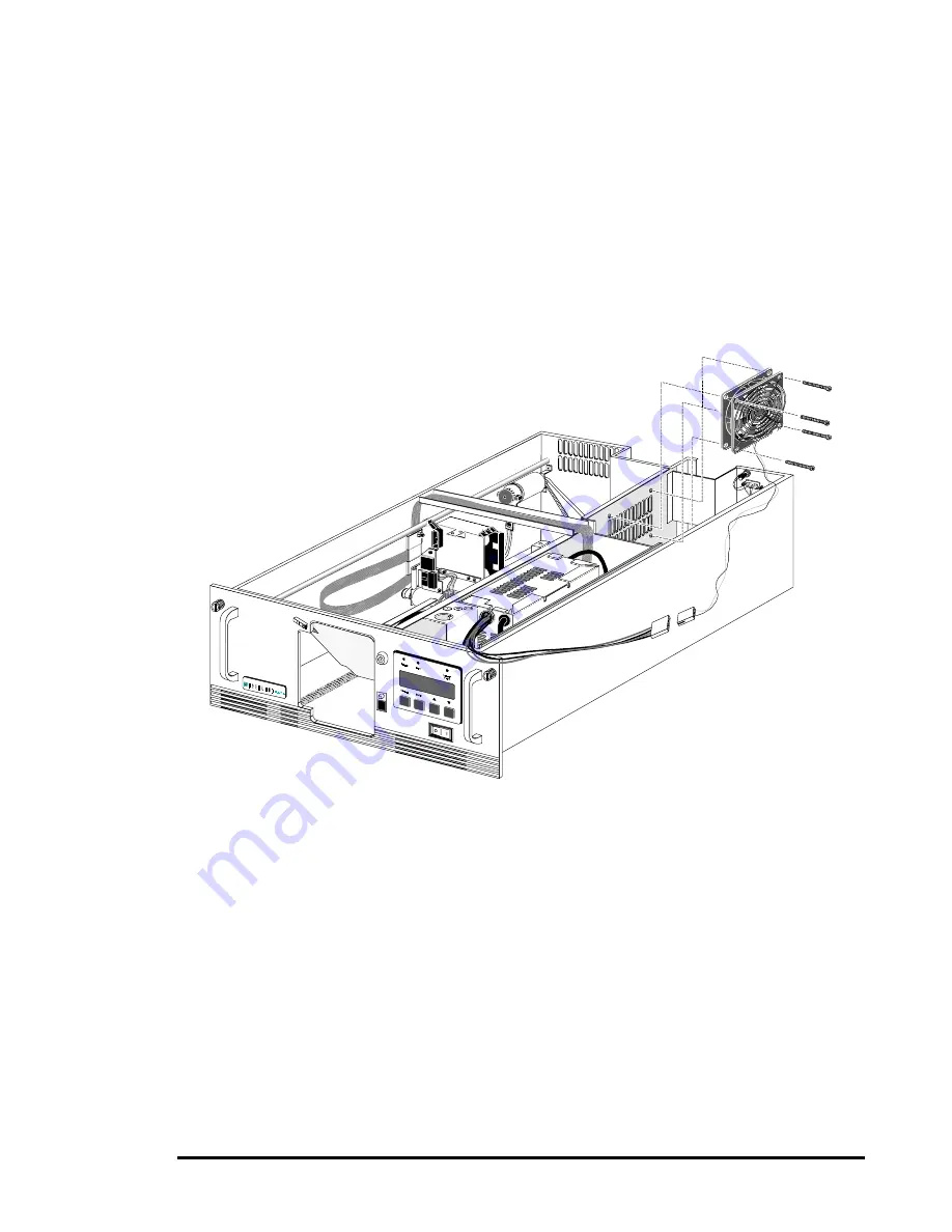
Refer to Figure 6-11.
1.
Remove the cover plate as described in this chapter.
2.
Remove the four M4 x 35 mm Phillips pan head screws and sems washers that
secure the fan to the bulkhead.
3.
Disconnect the fan power cable from the power supply connector.
4.
Remove the fan from the chassis.
Figure 6-11
Fan Assembly, Global Control and Capacity Modules
Replacement, Global Control and Capacity Modules
Refer to Figure 6-11.
1.
Orient the fan and finger guard against the right side of the bulkhead so that the fan
power cable is at the lower left.
2.
Install four M4 x 35 mm Phillips pan head screws with sems washers through the
loops on the finger guard and the holes at the four corners of the fan. Do not tighten
to more than 2-3 in-lb. Excessive pressure will break off the corners.
3.
Connect the fan power cable connector to the power supply connector.
4.
Replace the cover plate as described in this chapter.
Содержание DLT LibraryXpress Series
Страница 8: ......
Страница 16: ...8 Chapter 1 Introduction Figure 1 5 Global Control Module Rear View Figure 1 6 Base Module Rear View...
Страница 20: ......
Страница 52: ......
Страница 80: ......
Страница 92: ......
Страница 130: ......
Страница 134: ...126 Appendix A Specifications...
Страница 135: ...Appendix A Specifications 127 a p a c i t y C C a pa city C C...
Страница 136: ...128 Appendix A Specifications...
Страница 138: ......
Страница 140: ......


