031-331-B1-001, Rev. A (11/2015)
031-331-B1-001, Rev. A (11/2015)
14
15
Indications/Alarms, Morningstar TriStar MPPT-30 Charge Controller
with PT-10 Low Voltage Disconnect
Charge Control / Load Control
LEDs on the Morningstar TriStar MPPT-30 Charge Controller indicate battery state, operational status and alarm conditions as
listed in the table below. Detailed information regarding alarm states can be found in the
TriStar MPPT-30 Solar System Controller,
technical manual (p/n MS-000946 v05.1)
TriStar TS-MPPT-30 LED Indicators
General Transitions
LED Indications
Controller start-up
Green / Yellow / Red (one cycle)
Equalize request start
Green + Red / Green + Red / Green / Green
Equalize cancelled
Green + Red / Green + Red / Red / Red
Battery service is required*
All 3 LEDs blinking until service is reset
*Battery service notification is only enabled in custom settings
Battery Status (General State of Charge)
LED Indications
80% to 95%
Green
60% to 80%
Green + Yellow
35% to 60%
Yellow
0% to 35%
Red
Battery is discharging
Red
Absorption state
Green blinking (½ second on / ½ second off )
Equalization state
Green fast blink (2.5 times per second)
Float state
Green slow blink (1 second on / 1 second off )
Faults & Alarms
LED sequence; repeating until the fault is cleared
Over-temperature
Yellow / Red (sequencing)
Battery high voltage disconnect
Green / Red (sequencing)
DIP switch fault or DIP switch changed
Red / Yellow / Green (sequencing)
Self-test faults
Red / Yellow / Green (sequencing)
Custom settings edit
Red / Green / Yellow (sequencing)
Remote Temperature Sensor (RTS)
Green + Yellow / Red (sequencing)
Battery voltage sense failure
Green + Yellow / Red
System Startup,
Morningstar TriStar MPPT-30 Charge Controller
Before Startup:
• Verify the PV disconnect is open.
• Verify the Battery disconnect and any used battery string disconnect(s) are open.
• Verify the load disconnect is open.
Startup Procedure
1. Confirm the polarities of the PV module wiring and Battery string wiring are correct.
2. Close the connected battery string breakers (1 through 3).
3. Close the master battery disconnect. The LEDs on the charge controller will sequentially blink one cycle of Green-Yellow-Red, indicating
a successful startup.
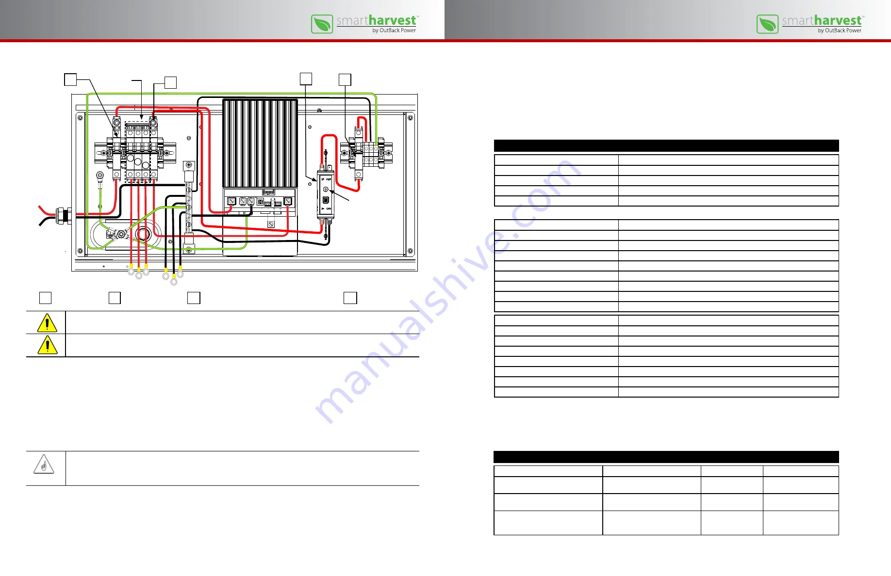
A
C
D
Illustration of Morningstar TriStar MPPT-30 Charge Controller courtesy of Morningstar Corp.
A
PV disconnect
B
Battery disconnect
C
Low voltage disconnect (LVD), Model PT10
D
Load disconnect
CAUTION: Hazard to Equipment
Reversed polarity will damage the charge controller.
CAUTION: Hazard to Equipment
Failure to close the battery breakers before closing the PV breaker will damage the charge controller.
Dual-color LED
indicates normal
operating state or
alarm state.
NOTE:
A battery must be connected to the TriStar MPPT to start and operate the controller. The controller will not operate only from
solar input.
4. Close the PV disconnect. The color and activity of the LEDs will indicate the state of charge of the battery string.
5. Close the Load disconnect. The green LED on the Low Voltage Disconnect device will be on solid indicating battery voltage is
within the disconnect (10.5 Vdc) and reconnect (12.5 Vdc) voltage limits as set by the factory.
6. Measure across the Load positive (+) and Load negative (–) on the charge controller to verify the battery voltage.
Battery
strings
B
1
2
3
Low Voltage Disconnect (Model PT10)
Event
Result
Indication
Action
Normal operation
Low voltage disconnect is closed;
voltage supplied to load
Green LED is on solid
None required
Battery voltage decreases to disconnect
level (10.5Vdc)
Low voltage disconnect opens and
removes load from batteries.
Red (Alarm) LED is on
solid.
Recharge batteries.
Battery voltage increases to reconnect
level (12.5Vdc)
Low voltage disconnect closes and
reconnects load to batteries.
Alarm LED switches
from Red to Green; LED
is on solid
Load reconnected;
No action required.
The dual-color LED on the PT-10 Low Voltage Disconnect indicates whether the unit is in normal operation or in an alarm state as
indated in the table below.


