


031-331-B1-001, Rev. A (11/2015)
031-331-B1-001, Rev. A (11/2015)
2
3
Site Characteristics
In the northern hemisphere, always orient the array to true south. In the southern hemisphere, always orient the array to true
north. To optimize power output, verify that no object, including fencing,
trees, buildings and/or other obstructions, will cause any
shading of the array.
Site Latitude Fixed Tilt Angle
0° to 25°
30°
25° to 30°
La5°
30° to 35°
La10°
35° to 40°
La 15°
> 40°
60°
Components that determine tilt
Simplified System Block Diagram
The PV module(s) convert solar energy into DC power which is then fed to the positive (+) and negative (–) terminals on the
charge controller. The design of the charge controller allows for uniform charging of the battery bank and prevents overcharging
conditions. The batteries provide power for loads appropriately rated for the battery string (12Vdc to 48Vdc).
PV Module Tilt
Refer to the accompanying table for recommended tilt angles. The tilt angle is set by the vertical distance (span) between the pole
channels, the selection of an attachment point (a, b, or c) and the length of the strut.
For comprehensive information regarding installation and assembly of the Side-of-Pole mounting rack, refer to DPW Solar's
Side-of-Pole Mount Assembly Instructions.
WARNING: Personal Injury
Use care while assembling the rack assembly. During the assembly procedure components could create hazards, obstructing
free movement and leading to serious bodily injury. These hazards are at head/eye level. The use of head and eye protection is
required.
IMPORTANT:
The SPM-1 racking system is designed for poles 2" to 3.5" in diameter. The SPM-2 and SPM-3 racking systems are designed for poles
3" to 4.5" in diameter.
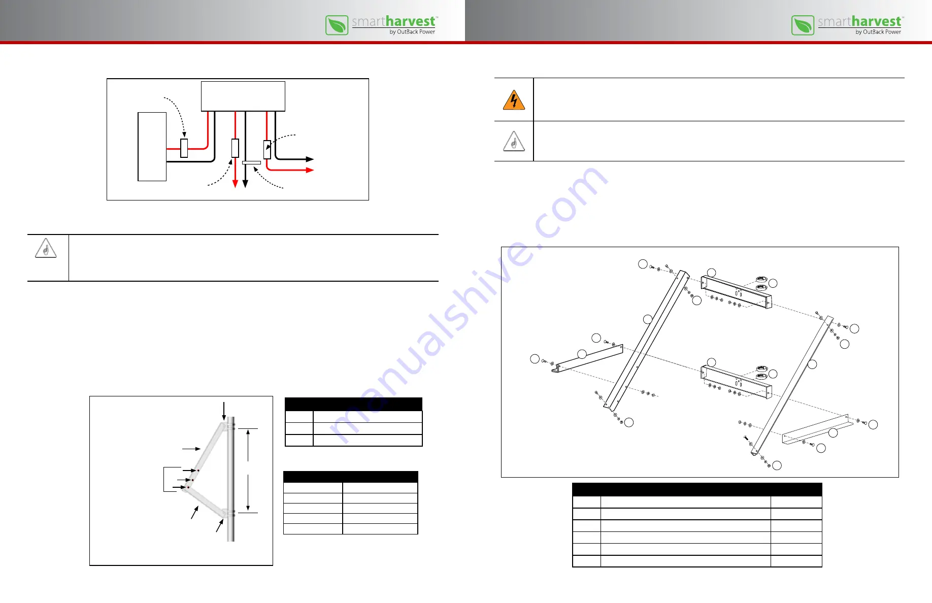
Mounting Rack Assembly
Item
Description
Quantity
1
Hose Clamp (standard)
4 per rack
2
Pole Channel
2 per rack
3
Module Rail (left and right)
2 per rack
4
3/8" x 1" hex bolt, lock washer, flat washers
6 sets per rack
5
Strut
2 per rack
6
1/4" x 3/4" hex bolt, lock washer, flat washers, nut
4 sets per rack
Item
Description
1
Pole Channel
2
Module Rail (left and right)
3
Strut (left and right)
Attachment Points
a
b
c
Span
2
1
1
3
Tools required for racking assembly:
• 7/16" wrench for 1/4" module hardware
• 9/16" wrench for 3/8" hardware
• Torque wrench (optional, recommended)
• Ratchet and extension bar
• Safety eyewear
• Safety headgear
PV
modules
Charge Controller
PV Module breaker
(+)
( –)
PV
BATT
LOAD
Load circuit breaker
Load (+)
Load (–)
(–)
(+)
(–)
(+)
(–)
(+)
Battery breaker
Negative bus bar
Battery string(s)
1
2
4
5
1
2
4
4
4
4
4
5
3
3
6
6
6
6
Illustration courtesy of DPW Solar / Preformed Line Products
Illustration courtesy of DPW Solar / Preformed Line Products
IMPORTANT:
The size and capacity of the system determine which charge controller,
either the SmartHarvest by OutBack
SCCM20-100 MPPT or Morningstar TriStar MPPT-30
, is installed in the system.
Verify the particular make and model in
the system and follow instructions in this and related product documentation