Installation
Requirements
o
The FXR and VFXR inverter/chargers are intended for
indoor installation only.
o
Ensure the mounting surface is strong enough to
handle 3 times the total weight of all the components.
o
The inverter has four 0.313" (8 mm) mounting holes
( ), one in each corner. Use fasteners in all corners.
o
Due to the variance in other mounting methods, OutBack
Power only endorses the use of FLEXware mounting
products. Use M6 × 20 mm machine screws, one per
corner, to attach the inverter to the mounting plate.
Follow the instructions with each mounting system.
o
Mount and secure each component before attaching any
wiring.
o
When the inverter is used with other metal chassis, make
sure that all chassis are grounded. Use either metal-to-
metal contact or separate ground wires as appropriate.
o
For more information, see the FXR
Installation Manual
.
See QR code above.
Tools Required
o
Wrench and socket sets; should include
Torque and ratchet wrenches
o
Wire cutters/strippers
o
Insulated screwdriver set (flat and Phillips);
should include
Miniature flat screwdriver for
A
UX
connections
o
Long-nose pliers
o
High-resolution voltmeter
900-0213-01-00 REV B
Do not copy or distribute without permission.
If it becomes necessary to
remove the Turbo Fan:
1. Remove the screws at the four
corners of the Turbo Fan.
2. Remove the compartment cover.
3. Unscrew the
A
UX
+
and
A
UX
–
terminal screws.
4. Remove the wires.
5. Remove the Turbo Fan.
IMPORTANT:
Use correct fasteners to secure the inverter to the
mounting surface. OutBack cannot be responsible for
damage to the product if it is attached with
inadequate fasteners.
IMPORTANT:
While sealed FXR models are more tolerant of incidental
dust and moisture than VFX models, none of these products
are intended for installation outdoors. Failure to adequately
protect the inverter from weather will void the warranty.
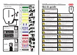
DC Cover or Turbo Fan Attachment
FXR inverters are equipped with either the DC
Cover or the Turbo Fan. To attach either cover,
put the cover in place and insert a screw at each
corner using a Phillips screwdriver. Make
certain the red and black battery terminals are
installed before attaching the cover.
As part of attaching the Turbo Fan, follow the
wiring instructions below.
Install the wires in the AC Wiring Compartment to make
the Turbo Fan operational. The
A
UX
+
and
A
UX
–
terminals receive the red (+) and black (–) wires.
Tighten with a Phillips screwdriver.
To safely run the wires into the AC compartment, pass
the wires through the notch in the compartment cover.
Notch
Edge of Cover
Compartment
If necessary, the green terminal block can be
unplugged by pulling it gently away from the AC board.
A
A
A
A
A
7.5"
(19.0 cm)
15.5"
(39.4 cm)
Make certain the
A
UX
programming is
correct for proper fan operation.
14.0"
(35.6 cm)
12.0"
(31.8 cm)
12.0"
(31.8 cm)
12.0"
(31.8 cm)
Materials in Box
o
Inverter
o
Quick Start Guide
(this document)
o
Battery terminal
covers, red/black
o
“WARNING ELECTRICAL SHOCK” sticker
o
AC plate
o
DC Cover (DCC) or Turbo Fan
o
Remote Temp. Sensor (RTS)
o
Silicone grease packet
Height with DCC
Height with Turbo Fan
1