Potentiostat
User Manual
Ossila.com
20
Ossila Limited © 2021
(II)
Save Directory
•
Sets the location in which to save the results.
•
This can be set either by:
I.
Manually typing the directory into the field.
II.
Copying and pasting it from your file explorer.
III.
Clicking the folder icon in the field, which will open a dialog box to allow the
selection of a folder to save to.
(III)
Sample Name
•
Sets the name of the comma-separated values (.csv) file in which the data will be saved.
I.
The name cannot contain the characters: \
/ : * ? “ < > |
(IV)
Save Selected
•
Clicking this button will manually save the measurement results of the active curve.
(V)
Save All
•
Clicking this button will manually save all the measurement results that are currently
displayed in the plot.
9.4
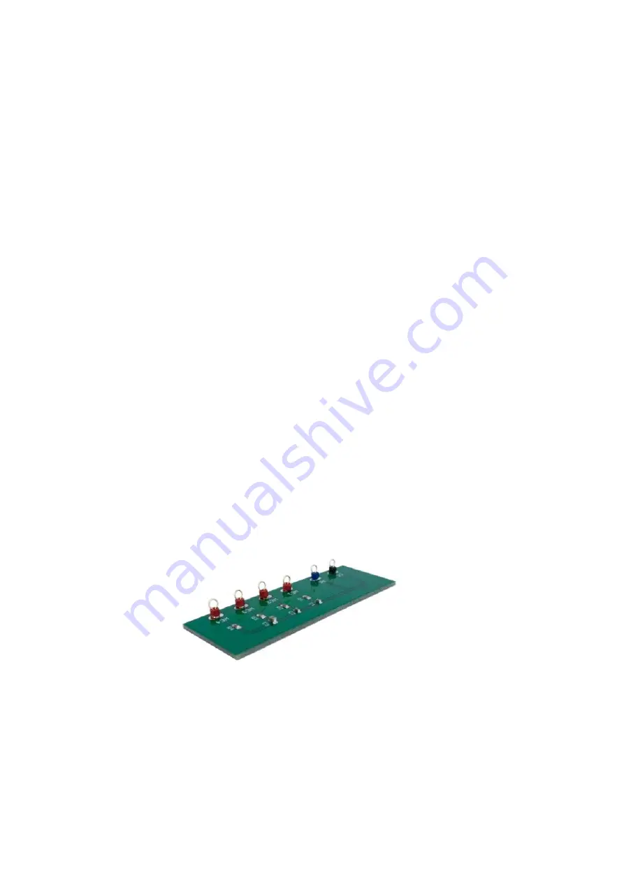
Test Cell Chip
The Ossila Potentiostat includes a Test Cell Chip, shown in
, which can be used to check
that your Potentiostat is operating correctly. It simulates an electrochemical cell by providing a
response which differs depending on the direction of the potential scan.
Figure 9.12.
Ossila Test Cell Chip.
9.4.1
Taking a Cyclic Voltammetry Measurement
1.
Plug in and turn on the Potentiostat.
2.
Use the cell connection cable to connect the Potentiostat to the same colour connectors
on the Test Cell Chip.
I.
Red connector to WE1, 2, 3, or 4.


