8
2.5 setting the latitude
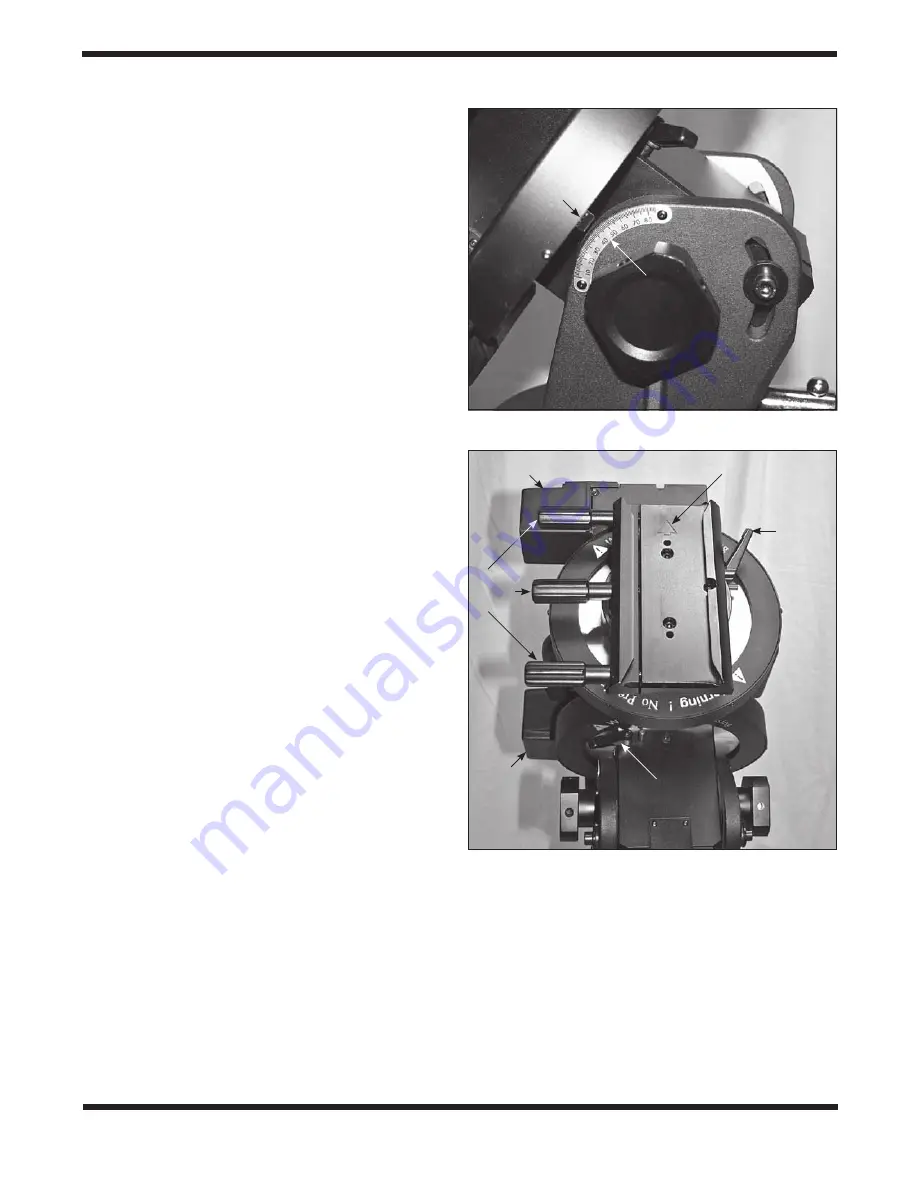
1. Make sure the two large altitude lock knobs and the two
altitude lock bolts are all loosened slightly.
2. Use the jackscrew handle to set the mount angle to your
latitude, referring to the latitude scale and pointer on the
left side of the mount
(Figure 14). (If you don’t know your
latitude, consult a geographical atlas or look it up on the
internet.) For example, if your latitude is 36° North, set
the pointer to 36.
3. Tighten the two large altitude lock knobs and the two
altitude lock bolts. Note that when you perform a polar
alignment, you will need to loosen these knobs and
bolts a very slight amount to permit adjustment. Then
you should lightly tighten them once polar alignment has
been established.
2.6 adjusting the azimuth
1. Make sure the azimuth locking bolts are slightly
loosened.
2. Use the azimuth adjustment knobs to move the mount in
either direction. To do this, loosen one knob by turning it
counterclockwise, then turn the opposite knob clockwise.
3. When you’ve rotated the mount to the desired position,
carefully tighten the two azimuth adjustment knobs. Then
lightly tighten the two azimuth locking bolts.
Note that when you perform a polar alignment, you will need to
loosen the azimuth locking bolts a very slight amount to permit
adjustment. Then you should lightly tighten them once polar
alignment has been established.
3. installing a Telescope on
the Mount
The HDX110 EQ-G mount is designed to hold a maximum
instrument payload of up to 110 lbs. This will vary with the
length of the telescope: for longer telescopes, which have a
longer moment arm, the maximum weight will be less.
3.1 installing the Telescope
1. Before installing a telescope, be sure that:
• The counterweight shaft is pointing toward the ground.
• The counterweights are installed on the counterweight
shaft and have been moved to the bottom end of the
shaft.
• The R.A. axis is secured by tightening the R.A. clutch
lever.
2. Release the Dec. clutch lever and rotate the saddle
until the arrow on it points either forward or to the right,
depending on your preference. It’s shown pointing
forward in
Figure 15. Then retighten the Dec. clutch lever.
3. Loosen the three saddle clamp knobs alternately until the
width of the groove is slightly wider than the width of the
dovetail bar on your telescope or telescope tube rings.
4. While holding the telescope securely, seat or slide the
dovetail bar of the telescope into the dovetail groove of
the saddle. Then, while still supporting the telescope with
one arm, tighten the three saddle lock knobs alternately
to secure the dovetail bar in the saddle.
3.2 Balancing the Telescope
To minimize stress on the motor drive system and ensure
smooth, accurate movement of a telescope on both axes of
the mount, it is imperative that the optical tube be properly bal-
anced. Proper balancing is critical for accurate tracking. We
will first balance the telescope with respect to the right ascen-
sion (R.A.) axis, then the declination (Dec.) axis.
Figure 14.
Refer to the latitude scale to set the mount to
the latitude of your observing or imaging site.
Figure 15.
When installing the telescope, the arrow on the
saddle should be pointing forward or to the right.
Latitude
scale
R.A. clutch lever
Pointer
Dec. motor housing
R.A. motor
housing
Saddle
clamp
knobs
Dec.
clutch
lever
Arrow


