11
USB-to-serial adapter. Check telescope.com for an available
adapter.
The 12V DC power jack on the hand controller is used only
for updating the firmware in the hand controller or for brows-
ing the object database without connecting to the telescope
mount. Do not connect the hand controller to a power source
when using the mount for normal operation!
5.5 Power supply requirements
The HDX110 EQ-G requires power from a 12V DC marine
battery or an AC-to-DC power supply with a 3-amp or higher
output current rating.
• Output Voltage: DC 11V (minimum) to DC 16V (maximum).
Voltage not in this range could cause permanent damage
to the motor controller board or the hand controller.
• Output Current: 4A for power supply with 11V output
voltage, 2.5A for power supply with 16V output voltage.
• Do not use an unregulated AC-to-DC adapter. When
choosing an AC adapter, it is recommended to use a
switching power supply with 15V output voltage and at least
3A output current.
• If the power voltage is too low, the motor controller will stop
the motors automatically.
6. Other HDX110 EQ-G
Features
6.1 auto-Home Function
The HDX110 EQ-G mount has two integrated home position
sensors. With the SynScan hand controller the mount can be
placed to the same home position after turning on the power.
For detailed information, refer to the SynScan Hand Controller
instruction manual.
6.2 auxiliary Encoder Function
Auxiliary encoders on both the R.A. and Dec. axes of the
HDX110 EQ-G mount enable it to continue tracking even
when the user unlocks the clutches and manually rotates the
mount in R.A. and Dec. With this feature, you can manually
operate the mount any time without worrying about losing the
mount’s GoTo star alignment status. When you want to oper-
ate the mount with the SynScan hand controller again, no re-
alignment is required; all that is needed is to re-lock the clutch
levers. This feature can be enabled or disabled in the SynScan
Hand Controller.
6.3 Permanent Periodic Error correction
The HDX110 EQ-G mount is equipped with an index on its
R.A. worm, thus the motor controller can keep tracking the cur-
rent position of the worm. After a proper PEC training routine,
in which the training data is stored in the motor controller per-
manently, a user can start the periodic error correction (PEC)
at any time to improve the tracking performance for astropho-
tography. A training process is not required in the next observ-
ing session (assuming that the polar alignment is always accu-
rate), thus this is a Permanent Period Error Correction (PPEC).
A user can train the mount by guiding either manually or elec-
tronically with auto-guiding. For detailed instructions, please
refer to the relevant section in the SynScan Hand Controller
instruction manual.
6.4 Batch Exposure Function
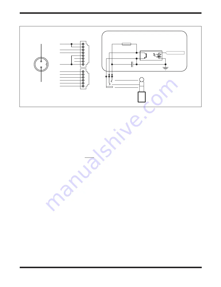
The HDX110 EQ-G mount has a SNAP port that can control
the shutter of a DSLR camera (see
Figure 17). Working with
the SynScan hand controller’s “Camera Control” function, you
can set the number of exposures, exposure duration, and
exposure interval for up to eight different sets of exposures.
For detailed information, refer to the SynScan Hand Controller
instruction manual.
Figure 19.
Schematic diagrams of the drive panel’s electronic interfaces.
2
3
4
1
5
6
7
8
HAND CONTROL
GND
Vpp+
RX(3.3V)
TX(3.3V)
2
3
4
1
5
6
AUTO GUIDE
GND
+5V
RA+
RA-
DEC+
DEC-
R
560
C
10uF/25V
SNAP
Optoisolator
GND
GND
Vpp+
POWER
Control Signal
Internal Circuit
GND
TRIGGER
DELAYED
TRIGGER


