background image

Introduction

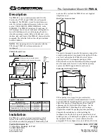
Your new Model D2260A Mini Mobile Base (

Figure 1

) is 

designed to give you a stable and mobile platform upon 

which to mount machinery and equipment with a variety 

of base dimensions and weights. 

Specifications

•  Minimum Inside Dimensions .............. 10

1

2

" x 14

1

2

"

•  Maximum Inside Dimensions ............. 21

1

2

" x 17

1

2

"

•  Maximum Weight Capacity ....................... 600 lbs

Tools

Tape Measure ....................................................1

Wrenches or Sockets 13mm ...................................2

Wrenches or Sockets 14mm ...................................2

Light Machine Oil (Optional) ...................... As Needed

Crowbar (Optional) .............................................1

Rubber Mallet (Optional) ......................................1

6" 2x4's (Optional) ..............................................2

6" 2x6 (Optional) ................................................1

12" 4x4 (Optional) ..............................................1

Inventory 

(Figure 2)


Qty

A.

  Swivel Casters ..............................................2

B.

  Fixed Casters ...............................................2

C.

  Left Corner Bracket .......................................1

D.

  Right Corner Bracket ......................................1

E

.  Right Corner Bracket w/Foot Post ......................1

F.

  Left Corner Bracket w/Foot Post .......................1

G.

  Side Rails 15

1

8

" Long .....................................2

H. 

Side Rails 10 

5

8

" Long ....................................2

I. 

Knobs M12-1.75 ............................................2

J. 

Feet ..........................................................2

K. 

  Hardware Bag (not shown)


     —Hex Bolts M8-1.25 x 16 (Brackets, Casters) ....... 32

— Lock Nuts M8-1.25 (Brackets) ....................... 16

— Lock Washers 8mm (Casters) ........................ 16

— Flat Washers 8mm (Casters) ......................... 16

— Hex Nuts M8-1.25 (Casters) .......................... 16

Figure 1. 

Model D2260A.

Figure 2

. Inventory.

A

B

D

E

F

G

H

I

J

C

Do  not  use  the  Model  D2260A  until 

you  have  read  and  understood  this 

instruction  sheet  and  completed  the 

entire  assembly  procedure.  Serious 

personal injury may occur if you ignore 

this warning. 

COPYRIGHT © MAY, 2009 BY WOODSTOCK INTERNATIONAL, INC.

WARNING: NO PORTION OF THIS MANUAL MAY BE REPRODUCED IN ANY SHAPE OR FORM WITHOUT

THE WRITTEN APPROVAL OF WOODSTOCK INTERNATIONAL, INC.

Printed in China

#11850BL

Model D2260A

Mini Mobile Base

Instruction Sheet

Phone #: (360) 734-3482 • Online Tech Support: [email protected] • Web: www.shopfox.biz

Summary of Contents for D2260A

Page 1: ... Left Corner Bracket w Foot Post 1 G Side Rails 151 8 Long 2 H Side Rails 10 5 8 Long 2 I Knobs M12 1 75 2 J Feet 2 K Hardware Bag not shown Hex Bolts M8 1 25 x 16 Brackets Casters 32 Lock Nuts M8 1 25 Brackets 16 Lock Washers 8mm Casters 16 Flat Washers 8mm Casters 16 Hex Nuts M8 1 25 Casters 16 Figure 1 Model D2260A Figure 2 Inventory A B D E F G H I J C Do not use the Model D2260A until you hav...

Page 2: ...r machine are not within the specifications of the Model D2260A mobile base DO NOT attempt to mount your machine onto this base Choose a larger Shop Fox mobile base such as the Model D2057A or D2058A that will accommodate the footprint of your machine If the footprint of the machine is too small for the mobile base complete Steps 2 3 assemble the mobile base then follow the instructions in Making ...

Page 3: ...hers and M8 1 25 hex nuts as shown in Figure 5 2 Mount each fixed caster to a corner bracket with the eight hole pattern using 4 M8 1 25 x 16 hex bolts 8mm flat washers 8mm lock washers and M8 1 25 hex nuts as shown in Figure 6 Orient the fixed casters so they point in the same direction that your machine will typically be moved see Figure 7 Mounting the fixed casters in the wrong direction will m...

Page 4: ...er bracket making sure the two long rails are parallel with one another and the two short rails are also parallel as shown in Figure 9 Note The rails may look different depending upon the configuration you have chosen If you are attaching your base to the Model D2259A Shop Fox Extension Kit refer to the instructions that came with your kit Note Before continuing with the next step you will have to...

Page 5: ...ts have been installed and tightened Loading a machine onto the base before completing assembly can result in the machine falling or tipping over resulting in serious personal injury 9 Thread a knob into the top of a foot post several turns then insert a foot into the bottom of the foot post as shown in Figure 12 The knob shaft should pick up the foot when it comes in close proximity since the top...

Page 6: ...orner brackets with the foot posts then slide the assembly up against the side of the machine that will be the front when pushed see Figure 13 4 Move the corner brackets as close to the machine base as possible 5 Secure the rail to the corner brackets with 4 M8 1 25 x 16 hex bolts and 8mm lock nuts as shown in Figure 14 Tip Thread the hex bolts into the rails but do not tighten the lock nuts again...

Page 7: ...ecessary to readjust the position of some of the fasteners once the machine is actually on the base assembly 8 Mount each fixed caster to a corner bracket with the eight hole pattern using 4 M8 1 25 x 16 hex bolts 8mm flat washers 8mm lock washers and M8 1 25 hex nuts as shown in Figure 17 Orient the fixed casters so they point in the same direction that your machine will typically be moved see Fi...

Page 8: ...s but do not tightening the lock nuts against the rails until instructed 12 Remove the rear rail corner bracket assembly from the 4x4 block 13 While the assistant steadies the machine remove the 4x4 block then set the machine on the ground 14 Put on safety glasses use a crowbar and some type of fulcrum to raise one of the side rails that is attached to the front corner bracket assembly then place ...

Page 9: ...de rails and under the machine Figure 22 Rear fixed caster assembly inserted into front caster assembly Front Rail Corner Bracket Assembly 6 2x4 Rear Fixed Caster Assembly Side Rail 18 Secure each side with 2 M8 1 25 x 16 hex bolts and 8mm lock nuts as shown in Figure 23 Tip Thread the hex bolts into the rails but do not tightening the lock nuts yet 19 Tighten the knobs enough to raise the corner ...

Page 10: ...e the wood screws to fasten the boards together from both sides 3 Allow 24 hours for the glue to dry before placing your machine on it 4 Place the base plate on the mobile base 5 Drill holes through the base plate and the metal plates at the corners of the mobile base 6 Secure the base plate to the mobile base with hex bolts hex nuts flat washers and lock washers as shown in Figure 26 Note Use 2 t...

Page 11: ...e mounted on the mobile base turn the knobs on the corner brackets counterclockwise so the feet clear the floor by at least 1 8 If the floor is uneven retract the feet completely to eliminate the chance of the pads dragging on the floor 3 Check to make sure the pathway is clear of all obstructions To avoid serious personal injury keep your hands and fingers clear of machine base and mobile base pi...

Page 12: ...D2260A001 SWIVEL CASTER 10 XPB03M HEX BOLT M8 1 25 X 16 2 XD2260A002 FIXED CASTER 11 XPW01M FLAT WASHER 8MM 3 XD2260A003 RAIL 10 5 8 LONG 12 XPLW04M LOCK WASHER 8MM 4 XD2260A004 RAIL 15 1 8 LONG 13 XPN03M HEX NUT M8 1 25 5 XPB03M HEX BOLT M8 1 25 X 16 14 XD2260A014 RIGHT CORNER BRACKET W FOOT POST 6 XPLN04M LOCK NUT M8 1 25 15 XD2260A015 RIGHT CORNER BRACKET 7 XD2271012 SHOP FOX LOGO LABEL 16 XD22...

Reviews: