PT-Link-LON
®
Technical Guide
PT-Link Interface
16
Using RUINET
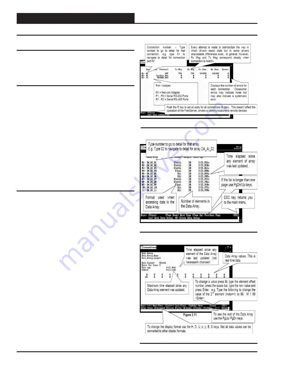
Figure 23: Data Array Overview Screen
Figure 22: Connection Overview Screen
Figure 24: Data Array Detail Screen
Using RUINET
Before continuing with the troubleshooting, make sure the PT-Link is
connected correctly and the RUINET software is installed, running, and
functioning correctly.
Verifying Proper Communications
From the
RUINET Main Screen
,
press
<O>
to go the
Connection
Overview Screen
. This screen supplies information on communication
between the PT-Link and remote devices. A number of aspect screens
are available, and some of the aspect screens have more than one page.
Use the space bar to toggle between aspects and use the
<PgUp>
and
<PgDn>
keys to toggle between pages of the same aspect. The
Connec-
tion Overview and Settings Aspect Screen
is shown in
Figure 22
.
The main purpose in this screen is to verify that messages and characters
are being transmitted and received. In addition, it shows the number of
communication errors. If the PT-Link connection “
03
” is the protocol
connection, verify that is communicating appropriately. If it is not, check
that the PT-Link LEDs are working properly, the unit is wired correctly,
and the PT-Link is confi gured correctly. If the number of errors is con-
stantly increasing, move to the
Error Screen
by
pressing
the
<Space
Bar>
3 times to fi nd out the cause of the errors. Use the
<PgUp>
and
<PgDn>
keys to toggle between pages of the
Error Screen
.
Verifying Proper Values
To verify that the correct values for each unit are being communicated
to the PT-Link, move to the
Data Array Overview Screen.
To get to the
screen,
press
<A>
from the
RUINET Main Menu
.
See Figure 23
for
screen details.
In the
Data Array Overview Screen
(
Figure 23
) you will be able to see
the data arrays of all the units connected to the PT-Link denoted by an
array name
“DA_XXX_IY”
—
Y
being the address of the unit minus
one. The Address of the unit is determined by a set of dip switches.
To view the values being communicated from a specifi c unit, move to
the
Data Array Detail Screen
(
Figure 24
) of the unit by entering the
number under which it is listed. For example, for the unit listed in the
third position,
enter
<03>
.
To understand what each value means, look at the Data Array Tables
for the desired unit type, VCM-X, SA, or VCM. You can change the
writable values from this screen by using the modify command. To use
the modify command,
press
<M>
from the
Data Array Detail Screen
and then
enter
the Offset you want to change followed by a space and
the new value.
Example:
To change the Cooling Supply Setpoint to 60 in the VCM,
press
<M>
,
enter
<58 60>
, and then
press
<Enter>
. This could be useful to
prove that the unit can take and keep the setpoints properly.


