background image

2

VCCX2 Controller Technical Guide

All manuals are also available for download from 

www.aaon.com/controlsmanuals.

www.aaon.com

VCCX2 CONTROLLER TECHNICAL GUIDE

REVISION AND DATE

CHANGE

Rev. 01N, January 20, 2020

Liquid Line 1-4 Solenoid relay configurations changed to A1,A2,B1,B2 Comp Run 

Status in relay table and in wiring illustrations

Rev. 01N, January 20, 2020

Added BI: 126 - Exhaust Fan / Return Fan Proof of Flow Alarm

Rev. 01N, February 13, 2020

Added 11 = OA Damper Calibration to BACnet

® 

AI:3

Rev. 01N, July 14, 2020

Miscellaneous minor edits

Rev. 01P, October 1, 2020

Added RSMZ module and BACnet

®

 parameters

Rev. 01P, October 1, 2020

Added Subcool Monitor Module and BACnet

®

 parameters

Rev. 01P, December 11, 2020

10-foot cable changed to 25-foot cable for E-BUS Outdoor Air and Humidity sensors

Rev. 01P, December 11, 2020

Revision to Sump Heater and Sump Drain Enable operation

Rev. 01P, December 11, 2020

Added BACnet

®

 AV:94 Sump Drain Override

Rev. 01P, January 21, 2021

Added SIG1 - Return Air Plenum Pressure Sensor and AOUT4 - Modulating 


Exhaust Damper to VCC-X EM1 Wiring

Rev. Q, March 24, 2021

Updated RSMZ Trendlog tables, updated labels, miscellaneous minor edits

Rev. R, May 26, 2021

Updated BACnet

®

 points to latest VCCX2 software, updated Appendix A figures, 

various cosmetic updates

AAON, Inc.

2425 South Yukon Ave.

Tulsa, OK 74107-2728

www.aaon.com

Factory Technical Support Phone: 918-382-6450

Controls Support Phone: 866-918-1100

All rights reserved. © May 2021 AAON, Inc. 

It is the intent of AAON

®

 to provide accurate and current 

product  information.  However,  in  the  interest  of  product 

improvement, AAON

®

 reserves the right to change pricing, 

specifications, and/or design of its product without notice, 

obligation, or liability.

AAON P/N: G039840, Rev. R

AAON

®

 is a registered trademark of AAON, Inc., Tulsa, OK. 

Danfoss VFD

®

 is a registered trademark of Danfoss 


Commercial Compressors, S.A., Tallahassee, FL

BACnet

®

 is a registered trademark of ASHRAE Inc., Atlanta, 

GA.

EBTRON

®

 is a registered trademark of Ebtron, Inc., Loris, 

SC.

GreenTrol

TM 

is a registered trademark of GreenTrol 


Automation, Inc. Loris, SC.

Paragon MicroTrans

EQ

 Series Airflow Monitoring Station is a 

registered trademark of Paragon Controls, Inc., Santa Rosa, 

CA.

White-Rodgers

®

 is a registered trademark of Emerson 


Climate Technologies, Inc., St. Louis, MO

Copeland Scroll™ is a registered trademark of Emerson 

Electric Co., Sidney, OH

Содержание AAON VCCX2

Страница 1: ...ontroller Code DT003800 001 SS1088 Version 1 02 and up Service Tool SD Code DT001240 001 SS1063 Version 1 11 and up System Manager SD Code DT002150 001 SS1068 Version 1 11 and up System Manager Touch Screen Limited Access DT004254 001 SS7013 ...

Страница 2: ...24 2021 Updated RSMZ Trendlog tables updated labels miscellaneous minor edits Rev R May 26 2021 Updated BACnet points to latest VCCX2 software updated Appendix A figures various cosmetic updates AAON Inc 2425 South Yukon Ave Tulsa OK 74107 2728 www aaon com Factory Technical Support Phone 918 382 6450 Controls Support Phone 866 918 1100 All rights reserved May 2021 AAON Inc It is the intent of AAO...

Страница 3: ... Air Temperature Sensor 32 Building Pressure Sensor 33 Remote SAT Reset 34 E BUS Outdoor Air Temperature Sensor 35 E BUS Outdoor Air Temperature and Humidity Sensor 36 E BUS Return Air Temperature and Humidity Sensor 37 Duct Static Pressure Transducer 38 Supply Fan VFD or Bypass Damper Actuator 39 Economizer Actuator or WSE Actuator 40 Modulating Heating Device 41 Building Pressure Control Outputs...

Страница 4: ...ypass Damper 75 Heating Mode 76 Ventilation Mode Remote Contact Control and Space Sensor Operation 77 IAQ Control Morning Warm Up and Cool Down and Single Zone VAV 79 Airflow Monitoring Preheater Low Ambient and Duct Static Press 81 Duct Static Setpoint Reset and Duct Static Pressure Control 82 Building Pressure Control and Exhaust Duct Static Pressure Control 83 MUA CAV MUA and Space Temperature ...

Страница 5: ...NFIGURATION 104 System Configurations 104 Stand Alone System Layout 105 Networked System Single Loop Layout 106 Networked System Multiple Loop Layout 107 APPENDIX B VCCX2 LCD SCREENS 108 Navigation Keys 108 Main Screens Map 109 Setting Screens 110 Status Screens 111 Alarm Screens 112 Output Override Screens 113 Air Balance Screens and Factory Test Mode Screen 114 APPENDIX C VCCX2 BACNET 115 VCCX2 ...

Страница 6: ...r Wiring 37 Figure 19 Static Pressure Transducer Wiring 38 Figure 20 Supply Fan VFD Wiring 39 Figure 21 Economizer Damper Actuator or WSE Valve Actuator Wiring 40 Figure 22 Modulating Heating Device Wiring 41 Figure 23 Building Pressure Control Output Wiring 42 Figure 24 Entering Water Temperature Sensor Return Air Plenum Pressure and Return Exhaust Proof of Flow 43 Figure 25 Entering Water Temper...

Страница 7: ...ce Tool SD Modular System Manager SD System Manager TS L and Prism 2 Software Operator Interfaces 64 Figure 46 VCCX2 Controller LED Locations 101 Figure 47 VCC X EM1 Expansion Module LED Locations 101 Figure 48 Typical Stand Alone System Layout 105 Figure 49 Typical Networked Single Loop System Layout 106 Figure 50 Typical Networked Multiple Loop System Layout 107 Figure 51 LCD Display and Navigat...

Страница 8: ...le Comp Status Trend Log 95 Table 10 RSMZ Module RSM Alarm Trend Log 95 Table 11 RSMZ Module VFD Status Trend Log 96 Table 12 RSMZ Module VFD Alarm 1 Trend Log 96 Table 13 RSMZ Module VFD Alarm 2 Trend Log 96 Table 14 VCCX2 Trend Log Bit Strings 98 Table 14 VCCX2 Trend Log Bit Strings continued 98 Table 14 VCCX2 Trend Log Bit Strings continued 99 Table 15 0 5V Temperature Sensor Voltage and Resist...

Страница 9: ...ht digital compressors Controls up to four sets of tandem VFD compressors Controls up to 12 stages of heat Modulating Cooling Output for Chilled Water Valve Control Modulating Heating Output Hot Water Valve Steam Valve SCR Electric Heat Control Full Integration with the AAON Refrigerant System Modules RSM Full Integration with the AAON MODGAS X Module Full Integration with the AAON MHGRV X Modulat...

Страница 10: ...n requires the use of modulating heating or cooling sources Space Temperature Control of High Percentage Outdoor Air Units This application allows the unit to be configured to use the space temperature to initiate Cooling and Heating Modes on units that are high percentage outdoor air or 100 outdoor air units Before entering the Space Vent Mode the VCCX2 will first determine if the Outdoor Air Tem...

Страница 11: ...and RH OE217 02 OE217 03 ASM01819 ASM01820 E BUS Digital Room Sensor No LCD Temp and RH OE217 04 ASM02221 E BUS Horizontal Outdoor Air Temperature and RH Sensor OE265 15 ASM01836 E BUS Vertical Outdoor Air Temperature and RH Sensor OE265 16 ASM01838 E BUS Return Air Temperature and RH Sensor OE265 17 ASM01840 E BUS CO2 Return Air Sensor Emulator Board OE365 07 EBSE ASM01623 E BUS CO2 Space Sensor ...

Страница 12: ...onnected depending on the size of the system There are two E BUS Expansion Ports which allow for the use of communicating sensors and the E BUS Modules The RSMV HP provides six analog inputs four binary inputs four relays and two analog outputs It connects with an E BUS cable to the VCCX2 Controller Pages 21 53 54 ASM02201 Refrigerant System Module for Digital Compressors The Refrigerant System Mo...

Страница 13: ... Reheat Expansion Module is designed to control one set of reheat valves The Reheat Expansion Module connects to the MHGRV X via an E BUS communication cable Connected together the Reheat Expansion Modules provide a system that allows the proper control of multiple sets of valves N A ASM01688 ASM01689 PREHEAT X and PREHEAT X EXT Modules The PREHEAT X and PREHEAT X EXT are designed to control fixed...

Страница 14: ...h Cable sold separately Page 28 ASM01831 E BUS CO2 Duct Mounted Sensor with Remote Pickup Tube Used with the VCCX2 Controller for duct mounted CO2 sensing applications Connects to the VCCX2 Controller with an E BUS cable of required length Includes Duct Mounted CO2 Sensor Integral Aspiration Box Airflow Pickup Tube and 10 ft EBC cable 4 3 2 1 3M Page 29 ASM01836 E BUS Horizontal Outdoor Air Temper...

Страница 15: ...embly The EBC SPOOL is bulk EBC cable that can be used with the EBC Bulk Connectors Pages 25 60 G018890 EBC Bulk Connectors Attaches to EBC Spool Cable Must be crimped using either the G034180 EBC Crimp Tool or one matching the requirements listed in the pricing list Includes EBC Bulk Connector N A G034180 EBC Crimp Tool Crimps the EBC Connectors for use with the EBC Spool Cable Includes EBC Crimp...

Страница 16: ... wall mounting When System Manager is to be mounted on a solid wall concrete we recommend you attach the System Manager to a standard handy box STATUS SETPOINTS SCHEDULES OVERRIDES ALARMS 7 8 0 DEC MINUS 9 4 5 6 1 2 3 ENTER ESC CLLAR DOWN UP PREV NEXT See the VCCX2 Controller Operator Interfaces SD Technical Guide ASM01874 CommLink 5 Communications Interface The CommLink 5 connects to your control...

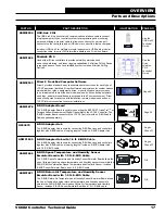
Страница 17: ... 64 ASM01878 E BUS Adapter Board The E BUS Adapter Board is used for connecting the EBTRON GreenTrolTM or Paragon Airflow Measurement Digital Transmitter to the VCCX2 Controller The E BUS Adapter Board connects to the VCCX2 Controller with an E BUS cable Cable supplied separately Page 50 G033970 E BUS Adapter Hub The E BUS Adapter Hub is used for connecting E BUS devices and controllers together w...

Страница 18: ...nting Wiring Instructions N A ASM01868 GPC XP Controller The GPC XP Controller is used for controlling equipment or processes that cannot be controlled using a standard HVAC controller Prism 2 computer front end software is used to interface with the GPC XP Controller functions The GPC XP Controller provides the flexibility to control schedule and or monitor equipment such as unit heaters exhaust ...

Страница 19: ...19 VCCX2 Controller Technical Guide Figure 1 VCCX2 Controller Components OVERVIEW VCCX2 Controller Components ...

Страница 20: ...20 VCCX2 Controller Technical Guide Figure 2 VCCX2 Controller Dimensions DIMENSIONS VCCX2 Controller 4 10 0 70 7 95 8 38 0 213 2 75 6 04 Note All Dimensions are in inches Note Depth is 1 50 inches ...

Страница 21: ...C POWER ONLY WARNING POLARITY MUST BE OBSERVED OR THE CONTROLLER WILL BE DAMAGED NOT USED 5 V 5 V COIL TEMP 1 COMP STATUS 1 SP HP COIL TEMP 2 COMP STATUS 2 GND GND NOT USED NOT USED GND TEMP 3 GND COIL TEMP SENSORS BINARY INPUTS E BUS RSM FOR VFD COMPRESSORS www aaon com SUCTION PRESSURE SENSOR HEAD PRESSURE SENSOR E BUS EXPANSION VALVE 1 EXPANSION VALVE 2 WHITE BLACK RED GREEN WHITE BLACK RED GRE...

Страница 22: ...R61 R57 R56 R54 R53 R49 R48 R46 R45 Q6 D21 D20 D19 D17 C24 2 1 Rc R35 R31 R29 R24 D13 D11 D10 D9 PWM R9 AOUT1 AOUT2 AOUT3 AOUT4 5621 OFF 1002 1002 1002 1002 1002 1002 47 4992 1002 1004 1002 1002 1004 1002 300 300 10uF 10uF 10uF 10uF 10uF 10uF 01uF 10uF 300 1002 1002 3650 R4 1002 R5 1002 J1 C26 OPTIONS R2 47 47 1001 1001 3650 3650 3650 5621 5621 5621 5621 YS102482 REV1 5 63 5 00 2 67 0 62 2 05 4 10...

Страница 23: ...LY10 RLY11 RLY12 RLY COM MADE IN USA RLY COM RLY COM RLY1 RLY2 RLY3 RLY4 RLY8 RLY7 RLY6 RLY5 24VAC GND EXPANSION BOARD YS102324 REV 2 RELAY 1002 1002 1002 1002 1002 1002 OFF 1uF 1000pF 5 00 0 20 5 63 6 06 2 76 5 52 2 05 0 71 4 10 Note All Dimensions are in inches Note Depth is 1 50 inches Figure 5 12 Relay E BUS Module Dimensions DIMENSIONS 12 Relay E BUS Module ...

Страница 24: ...ize for 24 VAC wiring should be 18 gauge 4 Minimum wire size for all sensors should be 24 gauge Some sensors require two conductor wire and some require three or four conductor wire 5 Minimum wire size for 24 VAC thermostat wiring should be 22 gauge 6 Be sure that all wiring connections are properly inserted and tightened into the terminal blocks Do not allow wire strands to stick out and touch ad...

Страница 25: ...orced Occupied Remote Forced Cooling Remote Forced Heating Remote Forced Dehumidification Emergency Shutdown Switch Supply Air Temp Sensor Mount in HVAC unit supply air stream Space Temperature Sensor GND AUX TEMP Return Air Temp Sensor Mount in HVAC unit return air stream Outdoor Air Temperature Sensor Building Static Pressure Sensor Plastic tubing to building pressure sensing locations Remote Su...

Страница 26: ...troller Technical Guide Note All Relay Outputs are normally open and rated for 24 VAC power only 1 amp maximum load Waterside Economizer Valve Figure 7 VCCX2 Controller Output Wiring WIRING VCCX2 Controller Outputs ...

Страница 27: ...er with the E BUS cable It can also be daisy chained with a CO2 sensor for applications requiring both a wall mounted CO2 sensor and one of the three Digital Room Temperature sensors The E BUS Digital Room Sensor should be mounted on the wall in an area that does not have drafts or is exposed to direct sunlight See Figure 8 this page for wiring details NOTE If using multiple E BUS sensors or modul...

Страница 28: ...perature sensor It should be mounted on the wall in an area that does not have drafts or is exposed to direct sunlight See Figure 9 this page for wiring details and installation notes A Duct Mounted E BUS CO2 Sensor can be used if desired instead of the E BUS CO2 Wall Mounted Sensor See Figure 10 page 29 for Duct Mounted E BUS CO2 Sensor wiring details NOTE If using multiple E BUS sensors or modul...

Страница 29: ...te Pickup Tube The Duct Mounted E BUS CO2 Sensor with Remote PickupTube is designed to be mounted in the return air duct of the HVAC unit and uses its integral aspiration box to sample the CO2 level in the duct See Figure 10 this page for wiring and installation details NOTE If using multiple E BUS sensors or modules the E BUS Hub or Adapter Board may be required Note The Duct Mounted E BUS CO Sen...

Страница 30: ...e floor in the space that is to be controlled The Space Temperature Sensor is available as a sensor only sensor with override button sensor with slide adjust and sensor with slide adjust and override configurations A Space Temperature Signal can be connected to AI1 for applications requiring a Space Temperature Setpoint See Figure 11 this page for complete Space Temperature Sensor wiring details S...

Страница 31: ...mperature Sensor is a 10K Type III thermistor sensor The Supply Air Temperature Sensor should be mounted in the unit discharge plenum or in the supply air duct A Supply Air Temperature Signal can be connected to AI3 for applications requiring a Supply Air Temperature Setpoint See Figure 12 this page for details Figure 12 Supply Air Temperature Sensor Wiring WIRING Supply Air Temperature Sensor ...

Страница 32: ... The Return Air Temperature Sensor should be mounted in the return air duct If the system has a Zoning Bypass Damper installed be sure the return air sensor is located upstream of the bypass duct connection A Return Air Temperature Signal can be connected to AI4 for applications requiring a Return Air Temperature Setpoint See Figure 13 this page for details Figure 13 Return Air Temperature Sensor ...

Страница 33: ...to the terminal labeled EXC Connect the GND side of the 24 VAC power source to the terminal labeled COM Connect the remaining terminal labeled OUT to AI5 on the VCCX2 Controller WARNING It is very important to be certain that all wiring is correct as shown in the wiring diagram below Failure to observe the correct polarity will result in damage to the VCCX2 Controller or Building Pressure Sensor F...

Страница 34: ...T Reset Signal ARemote SupplyAir Temperature Reset Signal can be connected toAI6 for applications requiring Remote Reset of the SupplyAir Temperature Setpoint See Figure 15 this page Figure 15 Remote SAT Reset Signal Wiring WIRING Remote SAT Reset ...

Страница 35: ... Outdoor Air Humidity the vertical or horizontal E BUS Outside Air and Humidity Sensor must be used instead See Figure 17 page 36 for details CAUTION Be sure to mount the Outdoor Air Temperature Sensor in the upright position in an area that is not exposed to direct sunlight and is protected from the elements The shaded area under the HVAC unit rain hood is normally a good location Unused conduit ...

Страница 36: ...n the upright position in an area that is not exposed to direct sunlight and is protected from the elements The shaded area under the HVAC unit rain hood is normally a good location Unused conduit opening s must have closure plugs installed and must be coated with sealing compound to provide a rain tight seal Water can damage the sensor NOTE If using multiple E BUS Sensors or Modules the E BUS Hub...

Страница 37: ...ir Temperature and Humidity Sensor Wiring 50 ft E BUS cable provided Note Connect the sensor to the VCCX2 Controller using the provided E BUS cable WIRING E BUS Return Air Temperature and Humidity Sensor CAUTION Be sure to mount the Outdoor Air Temperature Sensor in the upright position in an area that is not exposed to direct sunlight and is protected from the elements The shaded area under the H...

Страница 38: ...e Damper Actuator or Bypass Damper Actuator If you have configured the HVAC unit for constant volume operation this sensor is optional If it is installed on a constant volume unit it will not affect operation but rather will be used as a status only reading See Figure 19 this page for detailed wiring CAUTION It is strongly recommended that you use pneumatic tubing instead of relocating the sensor ...

Страница 39: ...10 VDC from AO1 on the VCCX2 Controller This signal output can be connected to either The Supply Fan VFD to modulate the supply fan speed A bypass damper for zoning applications See Figure 20 this page for detailed wiring CAUTION VFD units can cause large transient noise spikes which can cause interference to be propagated on other electronic equipment Use shielded wire wherever possible and route...

Страница 40: ... See Figure 21 this page for detailed wiring WARNING It is important to be certain that all wiring is correct as shown in the wiring diagram below Failure to observe the correct polarity will result in damage to the actuator or VCCX2 Controller Waterside Economizer WSE Valve The WSE valve must be wired as shown in Figure 21 this page for proper operation The WSE valve connects to AO2 on the VCCX2 ...

Страница 41: ...lating Steam Valve or is used for SCR Control of an Electric Heating Coil See Figure 22 this page for detailed wiring of the Modulating Heating Device WARNING It is very important to be certain that all wiring is correct as shown in the wiring diagram below Failure to observe the correct polarity could result in damage to the Modulating Heating Device or the VCCX2 Controller 1 10 VDC Note If the m...

Страница 42: ...he building pressure output The Building Static Pressure Sensor must be connected in order for the building pressure output to operate correctly CAUTION VFDunitscancauselargetransientnoisespikes that can cause interference to be propagated on other electronic equipment Use shielded wire wherever possible and route all sensor and controller wiring away from the VFD and the HVAC unit electrical wiri...

Страница 43: ...o used as a Building Static Pressure Sensor as shown on page 33 must be wired as shown in Figure 24 this page There are three terminal connections on the Pressure Sensor Connect 24 VAC to the terminal labeled EXC Connect the GND terminal on the EM1 Expansion Module terminal block to the terminal labeled COM Connect the remaining terminal labeled OUT to SIG1 on the EM1 EXC COM Tubing to RA plenum p...

Страница 44: ...Secure sensor element and thermal mastic strip to pipe with supplied wire tie Be sure to tighten wire tie snugly to ensure good thermal contact Figure 25 Entering Water Temperature Sensor WIRING VCC X EM1 Entering Water Temperature Sensor ...

Страница 45: ... factory for other manufacturer wiring instructions Economizer Damper Actuator Belimo Actuator shown Connect to Expansion Module s when used Exhaust Duct Static Pressure Sensor The ASM01640 Static Pressure Sensor plugs directly into the EM1 s Static Pressure port The Duct Static Pressure Sensor reading is used to determine current Exhaust Duct Static Pressure This Static Pressure reading is used t...

Страница 46: ... WARNING Observe Polarity All boards must be wired with GND to GND and 24 VAC to 24 VAC Failure to observe polarity will result in damage to one or more of the boards Expansion modules must be wired in such a way that the expansion modules and the controller are always powered together Loss of power to the expansion module will cause the controller to become inoperative until power is restored to ...

Страница 47: ... TERMINAL BLOCK VCC X E EXPANSION M1 AAON P N ASM01691 LABEL P N G040660 RC 2 Y1 3 COM 1 VCC X EM1 Expansion Module 18 30 VAC GND Line Voltage Chilled Water Valve Actuator VCC X E 1 Module 5 VA M correct total load Size transformer for Figure 28 Chilled Water Valve Actuator Wiring WARNING Observe Polarity All boards must be wired with GND to GND and 24 VAC to 24 VAC Failure to observe polarity wil...

Страница 48: ...ds must be wired with GND to GND and 24 VAC to 24 VAC Failure to observe polarity will result in damage to one or more of the boards Expansion modules must be wired in such a way that the expansion modules and the controller are always powered together Loss of power to the expansion module will cause the controller to become inoperative until power is restored to the expansion module Figure 29 Ret...

Страница 49: ...ther to provide the required inputs and outputs for your specific applications WARNING Observe Polarity All boards must be wired with GND to GND and 24 VAC to 24 VAC Failure to observe polarity will result in damage to one or more of the boards Expansion modules must be wired in such a way that the expansion modules and the controller are always powered together Loss of power to the expansion modu...

Страница 50: ...rity All boards must be wired with GND to GND and 24 VAC to 24 VAC Failure to observe polarity will result in damage to one or more of the boards Figure 31 EBTRON GTC116 or HTN104 Series GreenTrolTM GA 200 N Series and Paragon MicroTransEQ Series Airflow Measurement Digital Transmitter Wiring WIRING EBTRON GreenTrolTM and Paragon Digital Transmitters NOTE Only the EBTRON GTC116 or HTN104 series Gr...

Страница 51: ...ction Saturation Temperature Setpoint Modulates the Condenser Fan to maintain the Head Pressure Setpoint Modulates the Expansion Valves to maintain the Superheat Setpoint Provides alarms and safeties for the compressor and condenser operation Provides a 2 x 8 LCD character display and four buttons that allow for status of system operation system setpoints system configurations sensors and alarms a...

Страница 52: ...V can monitor a Head Pressure Transducer and control condenser fans to maintain a Head Pressure Setpoint The condenser fan will be controlled with a 0 10 VDC output signal Coil Temperature Sensors The Coil Temperature sensors are used to measure Coil Temperature after each evaporator coil line This temperature combined with the calculated Saturated Refrigerant Temperature is used to calculate the ...

Страница 53: ...e Transducer must be wired as shown in Figure 34 this page It is required for all comp ressorized VCCX2 applications 18 30 VAC GND Line Voltage Size transformer for correct total load RSMV 18 VA RSMV HP BK RD WH BK RD WH COMP STAT 1 COMP STAT 2 Coil Temp 2 Sensor Coil Temp 3 Sensor Coil Temp 4 Sensor COM COM COIL TEMP SWITCH POF Suction Pressure Sensor Head Pressure Sensor Coil Temp 1 Sensor Leavi...

Страница 54: ...g Water Temperature Sensor The Leaving Water Temperature Sensor is used to measure the Leaving Water Temperature when used on a WSHP unit CAUTION The Shraeder port used for installation of the suction pressure transducer should be located in a vertical position of the suction line to prevent refrigerant oil from accumulating in the sensor NOTE If there are two Compressors on a single circuit a tan...

Страница 55: ...ule for Digital Compressors RSMD can monitor and control up to two compressors and condensers The compressors can be in either a tandem or non tandem configuration The module is designed for R410 A refrigerant The RSMD is connected to the VCCX2 Controller Up to four RSMD s can be connected depending on the size of the system There are two E BUS Expansion Ports which allow the use of communicating ...

Страница 56: ... Head Pressure Control The Head Pressure Transducers are used to measure Head Pressure at the discharge line This Head Pressure is used to drive the condenser fans with a 0 10 VDC output signal to maintain a given Head Pressure Setpoint Compressor Discharge Sensors The Digital Compressor Discharge Temperature Sensor monitors the discharge temperature from the Digital Compressor to protect against ...

Страница 57: ...ring to the Reheat Expansion Module or VFD Compressor The RSMZ must be connected to an 18 30 VAC power source When wiring the RSMZ Controller its relay outputs must be wired as wet contacts connected to 24 VAC See Figure 38 this page for input wiring WARNING Observe Polarity All boards must be wired with GND to GND and 24 VAC to 24 VAC Failure to observe polarity will result in damage to one or mo...

Страница 58: ...oller Sensor USHX to maintain the Superheat Setpoint of each evaporator coil Provides alarms and safeties for the Compressor and Condenser operation Provides a 2 x 8 LCD character display and four buttons that allow for status of system operation system setpoints system configurations sensors and alarms and to change the module s address if necessary See Figure 39 this page for output wiring ALARM...

Страница 59: ...on status and alarm display This module must be configured to work with R410 A refrigerant and is configured for 667 PSI liquid line pressure transducers The Subcool Monitor must be connected to an 18 30 VAC power source See Figure 40 this page for wiring WARNING Observe Polarity All boards must be wired with GND to GND and 24 VAC to 24 VAC Failure to observe polarity will result in damage to one ...

Страница 60: ...and Dehumidification setpoint In addition up to sevenASM01687 Reheat Expansion Modules can be connected to the MHGRV X and to each other for additional Reheat Valve Control The MHGRV X directly connects to the VCCX2 Controller or indirectly using an E BUS Expansion Board via an E BUS cable See Figure 41 this page NOTE If using multiple E BUS sensors or modules a E BUS hub or adapter board may be r...

Страница 61: ...e Sensor High Limit Temperature Setpoint If the communication is interrupted between the MODGAS X and the VCCX2 Controller the MODGAS X will revert to stand alone operation For more information refer to the MODGAS X Technical Guide Supply Air Temperature Sensor Mount In Supply Air Duct Connect Supply Air Temperature Sensor to AI3 GND on VCCX2 Controller E BUS cable connects to VCCX2 Controller s E...

Страница 62: ...tage 3 Fixed Heat Stage 4 Proof of Ignition Signal 2 24 VAC Note 1 24 VAC must be connected so that all ground wires remain common 2 All wiring to be in accordance with local and national electrical codes and specifications Connect Supply Air Temperature sensor to AI3 and GND to VCCX2 Mount in supply air duct Supply Air Temperature Sensor The SAT OPTIONS jumper setting should be set to 1 Only one ...

Страница 63: ...X2 Controller Wiring PREHEAT X and PREHEAT X EXT Controller Wiring The ASM01688 PREHEAT X and ASM01689 PREHEAT X EXT are designed to control fixed stages of Preheat and optional modulating Preheat to maintain a desired Preheat Leaving Air Temperature Setpoint The PREHEAT X is limited to a 35 F Leaving Air Temperature Setpoint The PREHEAT X EXT has an extended Leaving Air Temperature Setpoint range...

Страница 64: ...nterfaces are available for programming and monitoring of the VCCX2 Controller See Figure 45 this page They are as follows Modular Service Tool SD Modular System Manager SD PC with Prism 2 Software installed and CommLink 5 System Manager TS L Touch Screen LimitedAccess Any of these devices or a combination of them can be used to access the status configuration and setpoints of any controller on yo...

Страница 65: ...ack SIG3 0 5 or 0 10 V 3 Return Air Plenum Pressure SIG1 0 5V 4 Exhaust Duct Static Pressure Duct Static Jack Binary Inputs 1 Return Exhaust Proof of Flow BIN1 Analog Outputs 0 10 or 2 10 VDC 1 Chilled Water AOUT1 2 Return Air Damper AOUT2 3 Return Air Bypass AOUT3 4 Motorized Exhaust Damper AOUT4 Relay Outputs 24 VAC 1 Configurable Relay R1 2 Configurable Relay R2 3 Configurable Relay R3 4 Config...

Страница 66: ...ne control method uses the 0 10VDC signal to control an Exhaust Fan VFD or an Exhaust Damper Actuator for Direct Acting Pressure Control applications In addition for Reverse Acting Pressure Control applications it can control an Outdoor Air Damper Actuator or in certain cases the VFD Supply Fan The other available control method is to configure one of the output relays as an exhaust fan output tha...

Страница 67: ...ans that you must configure the VCCX2 Controller to recognize these input signals VCCX2 Controller Outputs AO1 Main Supply Fan VFD Control Signal or Bypass Damper Control Signal This user adjustable voltage signal is used to modulate the Supply Fan VFD in VAV Single Zone VAV Filter Loading applications or Reverse Acting Building Pressure Control using the VFD In a VVT Zoning application this outpu...

Страница 68: ...ut AOUT1 Modulating Chilled Water Valve Actuator This output is used to control a Modulating Chilled Water Valve Actuator to maintain the Cooling Supply Air Temperature Setpoint This output provides a 0 10 or 2 10 VDC direct acting signal AOUT2 Return Air Damper Actuator Signal This output signal is a direct acting 2 10 VDC output signal that is used to modulate a ReturnAir DamperActuator in conju...

Страница 69: ...Economizer Minimum Setpoint position or if the damper moves above a user adjustable position setpoint 13 Heat Wheel Configure 1 Relay that turns heat wheel on when in occupied operation and turns heat wheel off when in Economizer Mode 14 Occupied Active If configured this relay will energize whenever the unit is in the Occupied Mode 15 Override Active If configured this relay will energize anytime...

Страница 70: ...or 100 Outdoor Air MUA or High Percentage Outdoor Air units Supply Air Temperature Selected for Cooling Only VAV units with optional Morning Warm Up Cool Down Supply Air Tempering Selected for VAV units maintaining a Cooling Setpoint with Cooling or Heating as required that may need heat to temper the Supply Air Temperature during very cold conditions Space Temperature with High Outdoor Air Provid...

Страница 71: ...Ms On units with digital orVFD compressors theVCCX2 Controller will utilize one or more Refrigerant System Modules RSMs Units with only fixed staged compressors that are doing dehumidification or that require head pressure control would also utilize an RSM Each RSM will control the compressors condensers and EXVs on Bitzer VFD compressor units for one or two refrigeration circuits Up to four RSMs ...

Страница 72: ...ntial between the Supply Air Temperature and the Active Supply Air Temperature Setpoint based on the Modulating Cooling Proportional Window The Maximum Signal Adjustment per time period is 10 and is not user adjustable The Minimum Signal Adjustment per time period is based on the Modulating Cooling Proportional Window The larger the Modulating Cooling Proportional Window the smaller the signal adj...

Страница 73: ...on Module for status monitoring Several Title 24 alarm conditions can also be displayed and are listed in the Alarms section of this manual Economizer Override Via BACnet As stated above the economizer must reach and remain at 100 before compressors will be allowed to stage on to meet the Cooling SupplyAir Setpoint Because of this 100 requirement if a value of less than 100 is written to BACnet po...

Страница 74: ...midification Mode a Heating Dehumidification Mode or a Vent Dehumidification Mode Any calls for Unoccupied Dehumidification use the same Dehumidification Setpoint as during the Occupied Mode since you never want humidity to get out of control Dehumidification Operation on DX Compressor Units Any DX unit doing dehumidification will utilize one or more Refrigerant System Modules RSMs Each RSM will c...

Страница 75: ... time the HVAC unit is ordered When Unit Heat is used for Reheat instead of Hot Gas Reheat the VCCX2 can activate the Heat Source s discussed in the Heating Mode section to maintain the SupplyAir Temperature at the Active Supply Air Temperature Setpoint When Unit Heat is used to supplement Modulating Hot Gas Reheat the Modulating Hot Gas Reheat Signal must reach 100 before Heating will be enabled ...

Страница 76: ...ing Signal is calculated by the differential between the Supply Air Temperature and the Active SupplyAirTemperature Setpoint based on the Modulating Heating Proportional Window The maximum signal adjustment per time period is 10 and is not user adjustable The minimum signal adjustment per time period is based on the Modulating Heating Proportional Window The larger the Modulating Heating Proportio...

Страница 77: ... with heating and cooling and there is no call for heating or cooling Remote Contact Control A Remote Contact Control option can be configured on the VCCX2 Controller to initiate the HVAC Modes of operation If this option is configured all Heating Cooling and Dehumidification modes will only be initiated based on 24 VAC wet contact closures on the Forced Heating Forced Cooling and Forced Dehumidif...

Страница 78: ...eating Mode or average the space temperature values and use that value to determine the mode of operation in both cases relative to the VCCX2 Space Temperature Setpoints It would use the highest humidity value relative to the Space Humidity Setpoint to initiate Dehumidification Mode The digital sensors each need to be configured with unique addresses 1 10 for this operation In this arrangement onl...

Страница 79: ...eed to be forced wide open during the Warm Up Mode you can configure one of the relay outputs to be used during this Mode If the Warm Up Mode is active the relay is activated This relay then becomes the Force Open Command for all VAV boxes to which it is wired Morning Cool Down Mode Operation When the VCCX2 Controller is configured for Morning Cool Down and switches to the Occupied Mode of Operati...

Страница 80: ...e Space Temperature rises to 72 5 F the fan will go to 100 Night Setback operation uses the same SZ VAV fan control logic however since the setbacks would normally be larger than the space reset range for the fan speed the fan will typically always be at 100 If the Hood On Off operation is used on a SZ VAV unit then during Hood On the mode enable will switch to the OutdoorAir Temperature Sensor us...

Страница 81: ...l disable during Economizer operation If the unit is a 100 outdoor air unit configured to use the Outdoor Air Sensor as the controlling sensor then the Heat Wheel Relay will disable in between the Outdoor Air Cooling and Heating Mode Enable Setpoints Outdoor Air Vent Mode Similarly on a unit configured for Space Control of High Percentage Outdoor Air and the unit is in Outdoor Air Vent Mode the wh...

Страница 82: ...nstalled however no control will occur Duct Static Setpoint Reset If the VCCX2 Controller is being used with AAON VAV box controllers in a VAV system the Duct Static Pressure Setpoint can be dynamically reset based on the most open VAV box associated with that unit As long as the most open box is less than 80 open the Duct Static Setpoint will be decrease at a user adjustable Reset Rate from the M...

Страница 83: ... is ignored and will not drive the Outdoor Air Damper open Supply Fan VFD Careful consideration should be made regarding the effects of potential reduced airflow when using this option If this option is selected the Supply Fan VFD Output AOUT1 Main Supply Fan VFD will be used to control the Supply Fan VFD to maintain the Building Pressure Setpoint in similar fashion to the Outdoor Air Damper contr...

Страница 84: ...omizer operation is enabled and with mode control initiated by the Space Temperature and Humidity Sensors Space Temperature Control of High Percentage Outdoor Air Units This option allows for Space Temperature control of 100 outdoor air units or units with a high percentage of outdoor air normally 50 or greater For this application you would configure Space Temperature w High Percentage OA for the...

Страница 85: ...ning Warm Up heating will be controlled to the Morning Warm Up Supply Air Setpoint In this operation if Night Setback operation will be initiated by a space sensor connected to the VCCX2 Controller then the Night Setback Cooling and Heating Offsets will be applied to the normal Occupied HVAC Mode Enable Setpoints not the Hood On Setpoints During Night Setback operation Heating will be controlled t...

Страница 86: ...ressor stage in the Heating Mode or the Cooling Mode of operation In Heating Mode Auxiliary Heat can be used with Compressor Heat to achieve theActive SupplyAir Heating Setpoint Auxiliary Heat can be Modulating Heat Staged forms of Heat A modulating form of heat followed by staged heat When Auxiliary Heat comes on in conjunction with a digital compressor heat stage the digital compressor will be l...

Страница 87: ...nd Condenser Valves will be closed Unit Cooling Mode If in Cooling Mode the Entering Water Temperature is below the Entering Air Temperature measured by the sensor connected to the Outdoor Temperature Sensor input by the Entering Water Control Deadband amount the WSE Valve will modulate to maintain the Cooling Supply Air Setpoint The Bypass and Condenser Valves will remain closed If theWSEValve op...

Страница 88: ... compressors are disabled during Heating Mode when the Outdoor Air Temperature is below the Compressor Heating Lockout Setpoint System Broadcasts You can configure the VCCX2 Controller to broadcast Building Pressure OutdoorAirTemperature OutdoorAir Humidity Space Temperature Space Humidity and CO2 to anyVCCX2 Controller that does not have one or more of these sensor s A CommLink 5 or MiniLink PD 5...

Страница 89: ...alarm will be cleared and the unit will restart operations Space Temperature Sensor Failure Alarm If the Space Sensor is configured as the controlling sensor Mode Enable Sensor or as the Reset Sensor and if the controller detects an open or short circuit on the Space Sensor Input or if the controller detects a missing E BUS digital space sensor then a Space Temperature Sensor Failure Alarm is gene...

Страница 90: ... cleared Missing Expansion Module Alarm Preheat X Board Missing EM1 Expansion Missing RSM Modules 1 4 Missing Reheat Board Missing ModGas Board Missing 12 Relay Board Missing If the controller is configured to have any of the above Expansion Boards Modules but the controller does not detect that board then the applicable alarm will occur If the board is properly detected after the unit has alarmed...

Страница 91: ...ay is energized but the Return Exhaust Fan Proving binary input on theVCC X EM1 Module does not see 24VAC a Return Exhaust Fan Proving Alarm will occur Dirty Filter Alarm A differential pressure switch is used to provide a 24 VAC wet contact closure to indicate a Dirty Filter status A Dirty Filter Alarm is then generated Dirty Filter needs to be configured for this alarm to occur Emergency Shutdow...

Страница 92: ... Economizing When it Should Economizer is enabled but not following the desired Economizer position commanded Economizer Is Economizing When It Should Not Economizer is not enabled but the feedback signal indicates a position more open than the minimum Economizer Damper Not Modulating Economizer is enabled but not within 10 of desired position within 150 seconds Economizer Excess Outdoor Air Filte...

Страница 93: ...xhaust Airflow CFM EXCFM kCFM Building Pressure BldPr WG Duct Static Pressure Static WG MHGRV Valve Position ReHeat MODGAS Valve Position ModGas Main Fan Speed VFD Signal FanVFD Economizer Position Econo Modulating Heat Signal ModHeat Building Pres Relief VFD Signal Relief Modulating Cooling Signal ModCool Sensor Alarms AlrmGrp1 Bit String Mechanical Alarms AlrmGrp2 Bit String Temp Limit and Sump ...

Страница 94: ...o the suction saturation temperature of Module 1 Compressor 1 while 3SucTmp2 refers to the suction saturation temperature of Module 3 Compressor 2 Several trend log items will use this pattern to identify the status of values related to certain modules and the compressors or condensers on those modules See Table 7 this page for RSMV RSMD trend logs and Table 6 this page for RSMZ trend logs RSMV RS...

Страница 95: ... MinRunPending 7 128 MinOffFlag 8 256 MinOffPending 9 512 StageUpConditionsMet 10 1024 StageDwnConditionsMet 11 2048 StageUpFlag 12 4096 StageDwnFlag 13 8192 CoilTempSatisfied RSMZ TREND LOG BIT STRINGS RSM ALARMS Item Bit Value Description 1RSMAlrms 2RSMAlrms 3RSMAlrms 4RSMAlrms 5RSMAlrms 6RSMAlrms 0 1 LowSuction 1 2 UnsafeSuction 2 4 TripHighDiscPSI_Comp1 3 8 Compressor1_NotRunning 4 16 Compress...

Страница 96: ...Z TREND LOG BIT STRINGS VFD ALARMS 1 Item Bit Value VFD Status Bit 0 1VFDAlrm1 2VFDAlrm1 4VFDAlrm1 5VFDAlrm1 0 1 Brake Check 1 2 Pwr Card Temp 2 4 Earth Fault 3 8 Ctrl Card Temp 4 16 Ctrl Word TO 5 32 Over Current 6 64 Torque Limit 7 128 Motor Th Over 8 256 Motor ETR Over 9 512 Inverter Overld 10 1024 DC under Volt 11 2048 DC over Volt 12 4096 Short Circuit 13 8192 Inrush Fault 14 16384 Mains ph L...

Страница 97: ...xt highest possible number which is 2 Dirty Filter So the Dirty Filter binary input is also currently active There is no remainder 2 2 0 so there are no more inputs that are active From the one value of 22 you are able to determine that three binary inputs were active when that trend item was recorded With a value of 86 you would have started with 64 Remote Dehumidification This would have left a ...

Страница 98: ...end Log Bit Strings VCCX2 TREND LOG BIT STRINGS Item Bit Value Description Alarm Group 4 0 1 Missing Refrigeration Module 1 1 2 Missing Refrigeration Module 2 2 4 Missing Refrigeration Module 3 3 8 Missing Refrigeration Module 4 4 16 Missing Preheater Module 5 32 Missing MHGR V or X Module 6 64 Missing MODGAS Module 7 128 Missing EM1 Expansion Module 8 256 Missing 12 Relay Expansion Module Alarm G...

Страница 99: ...gurable 7 128 12 Relay Exp Relay 8 Configurable 8 256 12 Relay Exp Relay 9 Configurable 9 512 12 Relay Exp Relay 10 Configurable 10 1024 12 Relay Exp Relay 11 Configurable 11 2048 12 Relay Exp Relay 12 Configurable 1A1Stat 1A2Stat 2A1Stat 2A2Stat 3A1Stat 3A2Stat 4A1Stat 4A2Stat 0 1 System On 1 2 Active Alarm 2 4 Disabled 3 8 Forced On 4 16 Forced Off 5 32 Outdoor Air Lockout 6 64 System Not Used 7...

Страница 100: ...D will light up and blink continuously toindicate theVCCX2 Controlleris communicating BACnet This yellow LED will light up and blink continuously to indicate BACnet communications Relay LEDs RLY1 This green LED will light up when the Supply Fan is enabled and will stay lit as long as the Supply Fan is active RLY2 RLY8 These green LEDs will light up when the relays are enabled and will stay lit as ...

Страница 101: ...101 VCCX2 Controller Technical Guide Figure 46 VCCX2 Controller LED Locations Figure 47 VCC X EM1 Expansion Module LED Locations TROUBLESHOOTING VCCX2 Controller and EM1 LED Diagnostics ...

Страница 102: ...2 746 135 57 2 3015 1 159 69 20 6 11906 2 717 140 60 2743 1 077 70 21 1 11652 2 691 145 62 7 2502 1 001 71 21 7 11379 2 661 150 65 6 2288 0 931 Space Supply Air Outdoor Air or Return Air Temperature Sensor Testing The following sensor voltage and resistance table is provided to aid in checking sensors that appear to be operating incorrectly Many system operating problems can be traced to incorrect...

Страница 103: ...4 17 2 40 2 17 5 00 4 25 2 50 2 25 Building Pressure Sensor Testing Instructions Use the voltage column Table 17 this page to check the Building Static Pressure Sensor while connected to a powered expansion module Read voltage with meter set on DC volts Place the minus lead on terminal labeled GND and the lead on terminal AI5 on the VCCX2 Controller BUILDING PRESSURE SENSOR Pressure Sensor W C Vol...

Страница 104: ...d and monitored from one or more of the available Operator Interfaces connected on the communications loop Networked System If you have 1 to 59 VCCX2 Controllers that require information sharing simply connect the controllers together using AAON communications wire or 18 gauge two conductor twisted pair with shield wire Belden 82760 or equivalent The Networked Single Loop System requires that eith...

Страница 105: ...105 VCCX2 Controller Technical Guide Figure 48 Typical Stand Alone System Layout APPENDIX A SYSTEM CONFIGURATION Stand Alone System Layout ...

Страница 106: ...nfigure The Controllers Line Voltage System Manager TS L Back View 18 30 VAC 6 VA R S T BLACK R Connect To T SH R Terminals On HVAC Unit Controller RED 18 30 VAC BROWN GND WHITE T BARE S 1uF YS102178 R4 WQVGA Graphical Interface WattMaster Controls Inc C24 R9 R7 R6 R5 R2 R1 C51 C39 C20 C19 C15 C14 C13 C12 C11 C10 C9 C7 C1 X3 8 00Mhz OFF 1002 1002 1002 1002 1002 1002 1002 1002 1002 1002 1002 1002 1...

Страница 107: ...C33 OFF T SH R 1002 1002 1002 1002 1002 1002 1002 1002 1002 1002 1002 1002 1002 1002 1002 1002 1002 1002 1002 1002 1uF 1uF 1uF 1uF 1002 1002 T SH R C24 COMM Line Voltage 18 30 VAC 15 VA Modular System Manager SD System Manager TS L Note The SMTS L Is An End User Interface Only It Cannot Be Used To Configure The Controllers Line Voltage System Manager TS L Back View 18 30 VAC 6 VA R S T BLACK R Con...

Страница 108: ...NTER key to navigate through the Main Menu Screen categories ALARM UP DOWN ENTER MENU EDITING Key Function UP or DOWN Use the UP or DOWN key to enter editing mode on a user adjustable screen Edit Mode is indicated by the underscore appearing on the screen NOTE Entering Edit Mode will also adjust the value up one UP key or down one DOWN key so you may have to readjust the value ENTER Use the ENTER ...

Страница 109: ... to scroll through the Status Screens Press to go to the Status Screen Press to go to Settings Screen Press to scroll through the Output Override Screens Press to scroll through the Alarms Press to go to the Output Override Screen Press to go to the Alarms Screen Press to go to the Air Balance Screen AIR BALANCE Press to scroll through the Air Balance Screens Press to go to the Factory Test Mode S...

Страница 110: ...nd 9 Settings Screens Refer to the following map when navigating through the Settings Screens From the Settings Screen press ENTER to scroll through the screens SETTINGS MAC ADDR 0 TO 127 BACnet CURRENT MAC ADDRESS Valid range is 0 to 127 Default is 1 The ENTER key moves the cursor between the digit fields starting with the ones field Once the cursor is under a field use the UP and DOWN arrow keys...

Страница 111: ...Occupied FRC OCC Force Occupied FRC UNOC Force Unoccupied REM OCC Remote Occupied ZONE HEAT ZONE COOL ZONE OVR Zone Override SPACE HUMIDITY 0 00 100 SAT TEMP XX X Supply Air Temperature 40ºF to 200ºF or 5ºC to 93ºC OAT TEMP XX X OUTDOOR AIR TEMPERATURE 40ºF to 200ºF or 5ºC to 93ºC OAT RH XX X OUTDOOR AIR HUMIDITY RAT TEMP XX X RETURN AIR TEMPERATURE 40ºF to 200ºF or 5ºC to 93ºC CO2LEVEL XX X CO2 L...

Страница 112: ...M SENSOR Return Air Airflow Alarm COOLING FAILURE Mechanical Cooling Failure Alarm HEATING FAILURE Mechanical Heating Failure Alarm FAN POF FAILURE Proof of Flow Interlock Alarm DIRTY FILTER Dirty Filter Alarm EMERG SHUTDOWN Emergency Shutdown Alarm ECONO FAILURE Title 24 Economizer Alarms HI SAT ALARM High Supply Temperature Cutoff Alarm LO SAT ALARM Low Supply Temperature Cutoff Alarm CONTROL TE...

Страница 113: ... 1 0 0 0 10 0 VDC MODULATING HEATING 0 0 to 10 0 Active Force Mode Press the UP and DOWN buttons to increase and decrease the value Default is 1 0 AUTO MOD COOL 1 0 0 0 10 0 VDC MODULATING COOLING 0 0 to 10 0 Active Force Mode Press the UP and DOWN buttons to increase and decrease the value Default is 1 0 AUTO EXHAUST 1 0 0 0 10 0 VDC EXHAUST FAN 0 0 to 10 0 Active Force Mode Press the UP and DOWN...

Страница 114: ... Default is 10 0 MIN FAN 0 0 VDC MINIMUM FAN VOLTAGE 0 0 to 10 0 vdc Press the UP and DOWN buttons to increase and decrease the value Default is 0 0 MAX EXH 10 0 VDC MAXIMUM EXHAUST VOLTAGE 0 0 to 10 0 vdc Press the UP and DOWN buttons to increase and decrease the value Default is 10 0 MIN EXH 10 0 VDC MINIMUM EXHAUST VOLTAGE 0 0 to 10 0 vdc Press the UP and DOWN buttons to increase and decrease t...

Страница 115: ...wisted pair with shield Use Belden 82760 or equivalent 18 30 VAC GND Line Voltage Size Transformer For Correct Total Load VCCX2 Controller 15 VA VCCX2 CONTROLLER Programming Note Use Settings Menu in the LCD display to program the BACnet settings SH T R Typical Terminal Blocks All Wiring To Be R To R SH G To SH G T To T ALARM MENU DOWN ENTER UP Figure 52 VCCX2 BACnet Connection to MS TP Network AP...

Страница 116: ...ACnet Properties for the VCCX2 Controller Parameter Object Description Limits Outdoor Air Dewpoint AI 19 Current Calculated Outdoor Air Dewpoint Temperature Supply Air Setpoint Reset Voltage AI 20 Supply Air Temp Setpoint Reset Input Signal Duct Static Pressure AI 21 Current Duct Static Pressure Duct Static Control Signal AI 22 Current Duct Static Control Signal Fan VFD Building Pressure AI 23 Cur...

Страница 117: ...ure Heat Pump Condenser A2 Superheat Heat Pump AI 61 Current Compressor A2 Superheat Temperature Heat Pump BACnet Properties for the VCCX2 Controller Parameter Object Description Limits A1 Expansion Valve Position AI 62 Current position of Compressor A1 Expansion Valve A2 Expansion Valve Position AI 63 Current position of Compressor A2 Expansion Valve Condenser A1 Expansion Valve Position AI 64 Cu...

Страница 118: ... Compressor C1 Suction Line Temperature Heat Pump BACnet Properties for the VCCX2 Controller Parameter Object Description Limits C2 Condenser Suction Temp Heat Pump AI 107 Current Compressor C2 Suction Line Temperature Heat Pump C1 Superheat Temperature AI 108 Current Compressor C1 Superheat Temperature C2 Superheat Temperature AI 109 Current Compressor C2 Superheat Temperature Condenser C1 Superh...

Страница 119: ...nt RSMZ 1 condenser fan signal RSMZ 1 VFD Comp Perc AI 152 Current RSMZ 1 VFD Compressor Percentage RSMZ 1 Discharge Pressure AI 153 Current RSMZ 1 discharge pressure BACnet Properties for the VCCX2 Controller Parameter Object Description Limits RSMZ 1 Suction Pressure AI 154 Current RSMZ 1 Suction Pressure RSMZ 1 Suction Line Temp AI 155 Current RSMZ 1 Suction Line Temperature RSMZ 1 Saturation T...

Страница 120: ...Temp 2 AI 193 Current RSMZ 3 Saturation Temperature 2 RSMZ 3 Superheat 2 AI 194 Current RSMZ 3 Superheat Temperature 2 BACnet Properties for the VCCX2 Controller Parameter Object Description Limits RSMZ 3 EEV Position 2 AI 195 Current RSMZ 3 EEV valve position 2 RSMZ 3 Warnings AI 196 Current RSMZ 3 Warnings See RSMZ Warnings Bits on page 132 RSMZ 3 Discharge Line Temp AI 197 Current RSMZ 3 discha...

Страница 121: ...aults Bits on page 132 RSMZ 5 Lockouts AI 231 Current RSMZ 5 Lockouts See RSMZ Lockouts Bits on page 132 RSMZ 6 Condenser Fan AI 232 Current RSMZ 6 condenser fan signal BACnet Properties for the VCCX2 Controller Parameter Object Description Limits RSMZ 6 Reheat Valve 1 AI 233 Current RSMZ 6 Reheat Valve 1 position RSMZ 6 Discharge Pressure AI 234 Current RSMZ 6 discharge pressure RSMZ 6 Suction Pr...

Страница 122: ...ature 2 reading APPENDIX C VCCX2 BACnet VCCX2 BACnet Parameters BACnet Properties for the VCCX2 Controller Parameter Object Description Limits SUB 2 Line Temp 3 AI 276 Subcooling Module 2 liquid line temperature 2 reading Enter Water Pump AI 277 Current status of Entering Water Temperature Return Plenum Pressure Status AI 278 Current value of the Return Plenum Pressure Sensor Return Plenum Control...

Страница 123: ...ime 1 F 0 6 C 30 F 16 6 C BACnet Properties for the VCCX2 Controller Parameter Object Description Limits Supply Air Heating Staging Window AV 15 In Heating Mode if the Supply Air Temperature rises above the Active Supply Air Heating Setpoint plus this Staging Window a Heating Stage will be deactivated after its Minimum Run Time 1 F 0 6 C 50 F 27 7 C Warm Up Target Temperature See AV 89 for Cool Do...

Страница 124: ...ient Protection Setpoint AV 36 Temperature at which the Low Ambient Relay will activate in the Occupied or Unoccupied Mode 30 F 34 4 C 70 F 21 1 C APPENDIX C VCCX2 BACnet VCCX2 BACnet Parameters BACnet Properties for the VCCX2 Controller Parameter Object Description Limits SAT Cool Setpoint Reset Source Low Limit AV 37 If doing Supply Air Setpoint Reset this is the Low Reset Source value in Coolin...

Страница 125: ...d Min Damper Position and the Max Position in High CO2 0 2000 BACnet Properties for the VCCX2 Controller Parameter Object Description Limits Indoor Humidity Setpoint Low Reset Limit AV 53 On indoor controlled non MUA units this is the Humidity setpoint at which the unit leaves Dehumidification During Coil Temp Reset this is the lowest Space RH value that corresponds to the High Coil Temp Setpoint ...

Страница 126: ...If the controller is configured for this operation the user can write a Space Sensor value 0 F 17 7 C 120 F 48 8 C BACnet Properties for the VCCX2 Controller Parameter Object Description Limits Space Humidity Value AV 73 If the controller is configured for this operation the user can write a Space Humidity Sensor value 0 100 Indoor RH Calibration Offset AV 74 If the Space Humidity Sensor is readin...

Страница 127: ...ture value to the VCCX2 and that value is lost 45 70 Sump Drain Override AV 94 Setting this value to 1 turns the Sump Drain relay on Setting this value to 0 sets the relay operation to Auto 1 On 0 Auto Return Plenum Pressure Setpoint AV 95 Current Return Plenum Pressure Setpoint BACnet Properties for the VCCX2 Controller Parameter Object Description Limits Return Plenum Pressure Deadband AV 96 Val...

Страница 128: ...sing economizer feedback Economizer Title 24 Failure A BI 29 Title 24 Air Temperature Sensor Failure Economizer Title 24 Failure B BI 30 Title 24 Not Economizing when it should BACnet Properties for the VCCX2 Controller Parameter Object Description Limits Economizer Title 24 Failure C BI 31 Title 24 Economizing when it should not Economizer Title 24 Failure D BI 32 Title 24 Damper Not Modulating E...

Страница 129: ... Expansion Board Relay 4 BI 63 Current Status of Configurable Relay 4 on 12 Relay Board BACnet Properties for the VCCX2 Controller Parameter Object Description Limits 12 Relay Expansion Board Relay 5 BI 64 Current Status of Configurable Relay 5 on 12 Relay Board 12 Relay Expansion Board Relay 6 BI 65 Current Status of Configurable Relay 6 on 12 Relay Board 12 Relay Expansion Board Relay 7 BI 66 Cu...

Страница 130: ...Status of Enable Signal to Compressor C2 BACnet Properties for the VCCX2 Controller Parameter Object Description Limits C1 Compressor Alarms BI 103 Indicates an RSM alarm is present on the C1 circuit C2 Compressor Alarms BI 104 Indicates an RSM alarm is present on the C2 circuit C1 2 Defrost Switch BI 105 Outside Coil C1 C2Temp Switch for Defrost Mode C1 2 Water Proof of Flow BI 106 C1 C2 Switch f...

Страница 131: ...Compressor F Compressor Running F2 BI 135 Current Run Status of Compressor F2 Return Fan Proving Status BI 136 Proof of Return Fan Airflow Binary Input Status IAQ Mode Active BI 137 Indicates that IAQ Mode is active Heat Wheel Defrost Active BI 138 Indicates Heat Wheel Defrost is active VCCX2 BACnet Property Identifier BACNETPropertyIdentifier VccxControlModeBits ENUMERATED Supply Air Cooling Only...

Страница 132: ...harge Pressure Comp 2 10 High Superheat 11 High Evap Temperature 12 Emergency Shutdown 13 RSMZLockoutsStatusBits ENUMERATED Suction Pressure System Lockout 0 Oil Boost Lockout 1 High Discharge Pressure System Lockout 2 Low Superheat System Lockout 3 High Superheat System Lockout 4 High Evap Temperature System Lockout 5 High Discharge Temp System Lockout 6 RSMZAlarms1StatusBits ENUMERATED Brake Che...

Страница 133: ... RSMZDriveStatusBits ENUMERATED Control_Ready 0 Control Not Ready 1 Control Ready 0 Drive_Ready 0 Drive Not Ready 1 Drive Ready 1 Enable 0 Coasting 1 Enable 2 Trip_Error 0 No Error 1 Trip 3 ErrorNoTrip 0 No Error 1 Error no trip 4 Reserved 5 Triplock_Error 0 No Error 1 TripLock must power cycle 6 Warning 0 No Warning 1 Warning 7 SpeedEqualsReference 0 Speed Reference 1 Speed Reference 8 BusControl...

Страница 134: ...andardized Device Profile L 4 BACnet Application Specific Controller B ASC Standard Object Types Supported Analog Input Optional properties supported Description Analog Value Optional properties supported Description Binary Input Optional properties supported Description Inactive_Text Active_Text Binary Value Optional properties supported Description Inactive_Text Active_Text Device Object Optiona...

Страница 135: ...d Duct Temperature Sensor 6 Probe Duct Temperature Sensor 12 Probe E EBC E BUS Cables 15 Described 15 E BUS Adapter Board 17 Described 17 E BUS Adapter Hub 17 E BUS Cables Described 15 E BUS CO2 Duct Sensor 14 Described 14 E BUS CO2 Wall Mounted Sensor 14 Described 14 E BUS Digital Room Sensor 14 E BUS Digital Room Sensor Temp Only Described 14 E BUS Outdoor Air Temperature Humidity Sensor 14 Econ...

Страница 136: ...rride Screens VCC X 113 P Part Number List 11 Pre Heater Operation 81 Pre Heat Relay Description 69 Prism 2 17 Described 17 Proof of Flow 65 R Reheat Relay Description 69 Relay Alarm Active 69 Relays Aux Heat 69 Cooling Stage 69 Economizer Active 69 Emergency Heat 69 Heating Stage 69 Low Ambient 69 Mod Heat Enable 69 Occupied Active 69 Override Active 69 Pre Heat 69 Room Sensor 14 S Screens Unit S...

Страница 137: ...ller Technical Guide V VCC X2 Alarm Screens 112 Main Screens Map 109 Override Screens 113 Settings Screens 110 Status Screens 111 VCC X2 Controller 12 Described 12 VCC X EM1 Expansion Module 12 13 Described 12 13 INDEX ...

Страница 138: ... www aaon com controlstechsupport NOTE Before calling Technical Support please have the model and serial number of the unit available PARTS For replacement parts please contact your local AAON Representative 2425 So Yukon Ave Tulsa OK 74107 2728 Ph 918 583 2266 Fax 918 583 6094 AAON P N G039840 Rev R Printed in the USA May 2021 AAON All Rights Reserved VCCX2 Controller Technical Guide G039840 Rev ...

Отзывы: