
104
VCCX2 Controller Technical Guide
System Configuration Options
The VCCX2 Controller can be used as a Stand-Alone System
(one VCCX2 Controller only), connected together on an
Interconnected System (multiple VCCX2 Controllers only) or
connected together on a Network System (multiple VCCX2
Controllers, VAV/Zone Controllers, or add-on controllers) to
form a complete Controls System that can be programmed and
monitored with one or more of the available Operator Interfaces.
Operator Interfaces
Operator Interfaces are designed to provide for programming
and monitoring of VCCX2 Controller(s) and/or any VAV/Zone
or add-on controller(s) connected to your system.
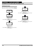
Stand-Alone System
The Stand-Alone System is used when you have a single VCCX2
Controller. Programming and status monitoring are accomplished
by selecting and installing one or more of the Operator Interfaces.
Interconnected System
The Interconnected System is used when you have multiple
VCCX2 Controllers on your job. With this system, you simply
connect the controllers together using AAON communications
wire or 18-gauge, two-conductor, twisted pair with shield wire
(Belden #82760 or equivalent). This allows for all controllers that
are connected on the communications loop to be programmed and
monitored from one or more of the available Operator Interfaces
connected on the communications loop.
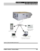
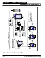
Networked System
If you have 1 to 59 VCCX2 Controllers that require information
sharing, simply connect the controllers together using AAON
communications wire or 18-gauge, two-conductor, twisted
pair with shield wire (Belden #82760 or equivalent). The
Networked Single Loop System requires that either a MiniLink
PD communication interface and/or CommLink communication
interface are purchased and wired into the communications loop
to the VCCX2 Controllers.
See
Figure 49, Page 106
for a Typical Networked Single Loop
System Layout diagram.
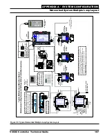
The Networked Multiple Loop system is used when you have
more than 59 VCCX2 Controllers and/or are using multiple
VCCX2 Controllers that are connected to VAV/Zone controllers.
These groups of controllers are broken up into multiple “Local
Loops” that connect to each other via the “Network Loop.”
Each individual MiniLink PD handles its specific local loop’s
communications requirements. The CommLink communications
interface handles all the communications between the individual
MiniLink PDs to form the network loop. Up to 60 local loops can
be connected together with this configuration. This provides the
capability for over 3500 controllers to be networked together.
See
Figure 50, page 107
for a Typical Networked Multiple Loop
System Layout diagram.
APPENDIX A - SYSTEM CONFIGURATION
System Configurations


