6 Connection
−
30
−
2-pulse input mode
The controller’s CW pulses are connected to the CW+ or the CW
−
, while the CCW
pulses are connected to the CCW+ or the CCW
−
.
•
When the CW pulse input changes from the ON to OFF, the motor will rotate one
step in the CW direction.
•
When the CCW pulse input changes from the ON to OFF, the motor will rotate
one step in the CCW direction.
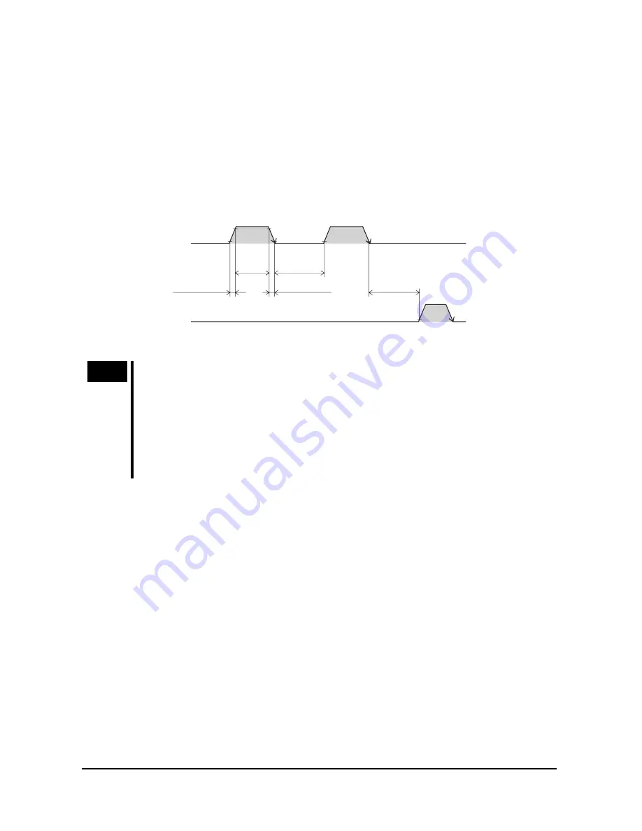
Use an input pulse signal with a waveform having a sharp rise and fall, as shown in
the figure:
90%
10%
5 µs or
more
50 (25) µs
or more
∗
2 µs or less
2 µs or less
DIR input
ON
OFF
ON
OFF
PLS input
100 µs
or more
ON: 4.5 to 5 V
OFF: 0 to 1 V
∗
( ) indicates the
CSD2140T
and
CSD2145T
.
Note
•
The interval for switching the motor direction represents the response
time of the circuit. Set this interval to an appropriate time after which the
motor will respond.
•
Always set the photocoupler to OFF when not inputting pulse signals.
•
Do not input CW pulse input and CCW pulse input at the same time. If
one of these pulses is input when the other is ON the motor will not run
properly.
•
AWO (All windings off) input
Use the signal only when the motor’s output shaft must be rotated manually for
position adjustment (ON: 4.5 to 5 V, OFF: 0 to 1 V.)
•
When the AWO input is turned ON, the driver stops supplying current to the
motor and the motor’s holding torque is lost. You to adjust the load position
manually.
•
When the AWO input is turned OFF, the current supply to the motor resumes,
thereby restoring the motor’s holding torque.


