background image


Power supply current capacity 

Model 

Input power 

supply voltage 

Power supply 

current capacity

DG60 

0.9 A or more 

EAS4 

1.4 A or more 

EAS6 

24 VDC±10% 

3.1 A or more 


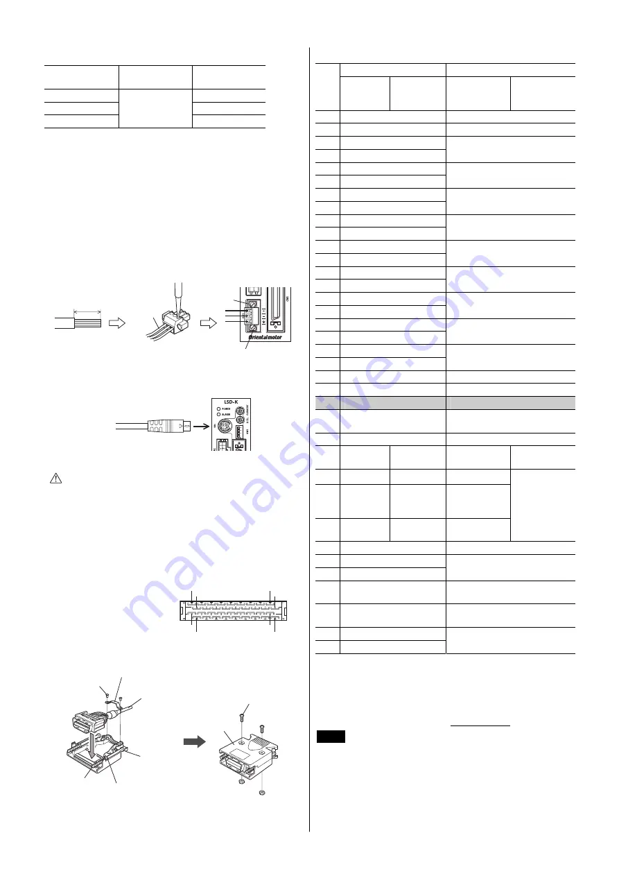
CN1 

1. 

Strip the insulation cover of the lead wire by 7 mm (0.28 in.) 

2. 

Insert each lead wire into the CN1 connector and tighten the 
screw using a screwdriver. 
Connector screw size: M2 
Tightening torque: 0.22 to 0.25 N·m (31 to 35 oz-in) 

3. 

Insert the CN1 connector into CN1 on the driver and tighten the 
screws. 
Connector screw size: M2.5 
Tightening torque: 0.4 N·m (56 oz-in) 

7 mm (0.28 in)

CN1 connector

Tightening torque: 0.4 N·m (56 oz-in)

Lead wire

CN1


CN4 

Connect to CN4

Cable for 

OPX-2A

 or

communication cable for data 

setting software


Caution


The power supply connector (CN1), data edit 
connector (CN4) and I/O signals connector (CN5) 
are not electrically insulated. When grounding the 
positive terminal of the power supply, do not 
connect any equipment (PC, etc.) whose negative 
terminal is grounded. Doing so may cause the 
driver and these equipment to short, damaging 
both. 


CN5 

Connector pin assignment 

(viewed from soldering side) 

1

2

17

18

19

20

35

36


• 

Assembling the connector 

I/O signal cable

Cable clamp

Screw (M2.5)

Case

Connector

Place the spring
washer outside
the case.

Screw (M2)

Screw (M2.5)
Tightening torque:
0.5 to 0.55 N·m 
(71 to 78 oz-in)

Align the washer in the
depression in the case.


• 

Pin assignment 

 Operating 

mode 

Name 

Pin 

No.

Positioning 
operation 

Push-motion 

operation


1

3


Positioning 

operation 

Push-motion 

operation

 ∗

1

3


2 GND 

Ground 

connection 

3 ASG+ 

4 ASG


A-phase pulse output 

(Line driver) 

5 BSG+ 

6 BSG


B-phase pulse output 

(Line driver) 

7 TIM1+ 

8 TIM1


Timing output (Line driver) 

9 ALM+ 

10

ALM


Alarm output 

11

WNG+ 

12

WNG


Warning output 

13

END+ 

14

END


Positioning completion output 

15

READY+/AL0+

1


16

READY

/AL0

1


Operation ready complete 

output/Alarm code output 0 

17

TLC+/AL1+

1


18

TLC

/AL1

1


Torque limit output/ 

Alarm code output 1 

19

TIM2+/AL2+

1


20

TIM2

/AL2

1


Timing output (Open collector)/

Alarm code output 2 

21

GND Ground 

connection 

22

IN-COM Input 

common 

23

C-ON

2


Current ON input


24

CLR/ALM-RST 

Deviation clear input/ 

Alarm reset input 

25

CCM 

Current control mode ON input

26

CS 

T-MODE

1

3


Resolution 

selection input 

Push-motion 

operation ON

27

 M0

1

3


28

RETURN

M1

1

3


Return to 

electrical home 

operation 

29

P-RESET

M2

1

3


Position reset 

input 

Push-current 

setting 

selection input

30

FREE Excitation 

OFF 

31

CW+/PLS+ 

32

CW

/PLS


CW pulse input/ 

Pulse input (+5 V or line driver)

33

CW+24 V/PLS+24 V 

CW pulse input/ 

Pulse input (+24 V) 

34

CCW+24 V/DIR+24 V 

CCW pulse input/ 

Direction input (+24 V) 

35

CCW+/DIR+ 

36

CCW

/ DIR


CCW pulse input/ Direction input 

(+5 V or line driver) 

∗1 

The signal will become effective if the applicable setting has been 
changed using the 

OPX-2A

 or 

MEXE02

∗2 

Factory setting of the C-ON input logic is "normally open." Be sure to 
turn the C-ON input ON when operating the actuator. Set the C-ON input 
logic to "normally closed" when the C-ON input is not used.


∗3 

These signals are used to perform push-motion operation. Do not set 
with the 

DG

  Series. Refer to the USER MANUAL for details. 


Note

• 

The driver I/O signals of the 

DG

 Series and 

EAS


Series are in common with those of the 

AR

 Series, 

but the signals are not compatible with the drivers of 
other series. Do not connect the I/O signals with pin 
assignments of other series. 

• 

Do not perform push-motion operation or sensorless 
return-to-home operation with the 

DG

 Series. 

Doing so may result in damage to the actuator.


Содержание LSD-K

Страница 1: ...0 3 C3 EN 55011 group 1 class A EMS Immunity Tests Radiation Field Immunity Test Electrostatic Discharge Immunity Test Fast Transient Burst Immunity Test Conductive Noise Immunity Test EN 61000 6 2 EN...

Страница 2: ...SM6 K EAS6 M K EASM6 MK LSD K DG60 EAS4 EAS6 DGM60 EASM4 EASM6 LSD K DC24 V 0 9 A 1 4 A 3 1 A 0 88 A 1 48 A 2 55 A SW1 No 2 SW1 No 3 No 4 SW1 No 1 CN4 CN2 POWER LED ALARM LED CN5 CN1 CN1 DIN POWER LED...

Страница 3: ...mm 35 mm 25 mm 90 mm DIN DIN DIN DIN DIN DIN DIN 10 20 N DIN DC24 V 10 GND FG CN4 OPX 2A MEXE02 CN1 CN2 CN5 0 3 0 35 N m 1 2 1 AWG24 16 0 2 1 25 mm2 2 AWG28 26 0 08 0 14 mm2 POWER LED EAS DC24V GND 20...

Страница 4: ...ALM 10 ALM 11 WNG 12 WNG 13 END 14 END 15 READY AL0 1 16 READY AL0 1 0 17 TLC AL1 1 18 TLC AL1 1 1 19 TIM2 AL2 1 20 TIM2 AL2 1 2 21 GND GND 22 IN COM 23 C ON 2 24 CLR ALM RST 25 CCM 26 CS T MODE 1 3...

Страница 5: ...8 8 A 68 8 3 25 0 B 75 0 4 31 3 C 81 3 5 37 5 D 87 5 6 43 8 E 93 8 7 50 0 F 100 ms ms 0 0 8 30 1 1 9 50 2 2 A 70 3 3 B 100 4 5 C 120 5 7 D 150 6 10 E 170 7 20 F 200 1 OFF OFF ON OFF ON OFF ON ON 1000...

Страница 6: ...W CCW 360 1000 B A EAS 0 01 mm 6 mm mm 6 6 mm 600 0 01 1000 0 006 A1 5 10 B 3 10 CW CW r min 1000 100 mm s 30 3 mm s ms 1000 r min 50 2 m s 2 100 1 m s 2 r min 60 6 mm s 30 3 mm s JOG r min 1000 100 m...

Страница 7: ...mm s 30 6 mm s ms 1000 r min 100 2 m s 2 100 2 m s 2 r min 30 6 mm s 30 6 mm s JOG r min 500 100 mm s 30 6 mm s JOG ms 1000 r min 100 2 m s 2 100 2 m s 2 JOG r min 30 6 mm s 30 6 mm s mm 1000 B A mm r...

Страница 8: ...t ORIENTAL MOTOR CO LTD 2012 http www orientalmotor co jp TEL 0120 911 271 9 00 18 30 TEL 0120 925 410 FAX 0120 925 601 TEL 0120 925 420 FAX 0120 925 602 TEL 0120 925 430 FAX 0120 925 603 8 00 20 00 9...

Страница 9: ...an enclosure For the driver power supply use a DC power supply with reinforced insulation on its primary and secondary sides EMC Directive This product has received EMC compliance under the conditions...

Страница 10: ...Input Voltage DC24 V Input Current 0 9 A 1 4 A 3 1 A Output current 0 88 A 1 48 A 2 55 A Names and functions of parts Current setting switch Speed filter setting switch Control mode select switch SW1...

Страница 11: ...it Hang the hook at the rear to the DIN rail and push in the driver After installation fix the both sides of the driver with the end plate Hook DIN rail DIN lever Removing from DIN rail Pull the DIN l...

Страница 12: ...ng output Line driver 9 ALM 10 ALM Alarm output 11 WNG 12 WNG Warning output 13 END 14 END Positioning completion output 15 READY AL0 1 16 READY AL0 1 Operation ready complete output Alarm code output...

Страница 13: ...haft can be set using the resolution switches OFF OFF ON OFF ON OFF ON ON Resolution 1000 P R Factory setting Resolution 500 P R Resolution 10000 P R Resolution 5000 P R Pulse input mode The pulse inp...

Страница 14: ...ries An example to set the resolution minimum travel amount to 0 01 mm is shown below represents parameters to be changed Ball screw lead 6 mm Setting example Initial value Setting items Setting value...

Страница 15: ...rical home operation Starting speed of return operation r min 30 6 mm s 30 6 mm s Operating speed of JOG operation r min 500 100 mm s 30 6 mm s Acceleration and deceleration rate of JOG operation ms 1...

Страница 16: ...other countries Copyright ORIENTAL MOTOR CO LTD 2012 Please contact your nearest Oriental Motor office for further information Technical Support Tel 800 468 3982 8 30 A M to 5 00 P M P S T M F 7 30 A...

Отзывы: