4
Installation
Location for installation
The driver has been designed and manufactured to be installed
within another device. Install them in a well-ventilated location that
provides easy access for inspection. The location must also satisfy
the following conditions:
•
Inside an enclosure that is installed indoors (provide vent holes)
•
Operating ambient temperature 0 to +55 °C (+32 to +131 °F)
(non-freezing)
•
Operating ambient humidity 85% or less (non-condensing)
•
Area that is free of explosive atmosphere or toxic gas (such as
sulfuric gas) or liquid
•
Area not exposed to direct sun
•
Area free of excessive amount of dust, iron particles or the like
•
Area not subject to splashing water (rain, water droplets), oil (oil
droplets) or other liquids
•
Area free of excessive salt
•
Area not subject to continuous vibration or excessive shocks
•
Area free of excessive electromagnetic noise (from welders,
power machinery, etc.)
•
Area free of radioactive materials, magnetic fields or vacuum
•
1000 m (3300 ft.) or lower above sea level
Installation method
The driver is designed so that heat is dissipated via air convection
and conduction through the enclosure. Install the driver onto an
appropriate flat metal plate having excellent vibration resistance and
heat conductivity. [made of aluminum, 200×200×2 mm
(7.87×7.87×0.08 in.) or equivalent] When two or more drivers are to
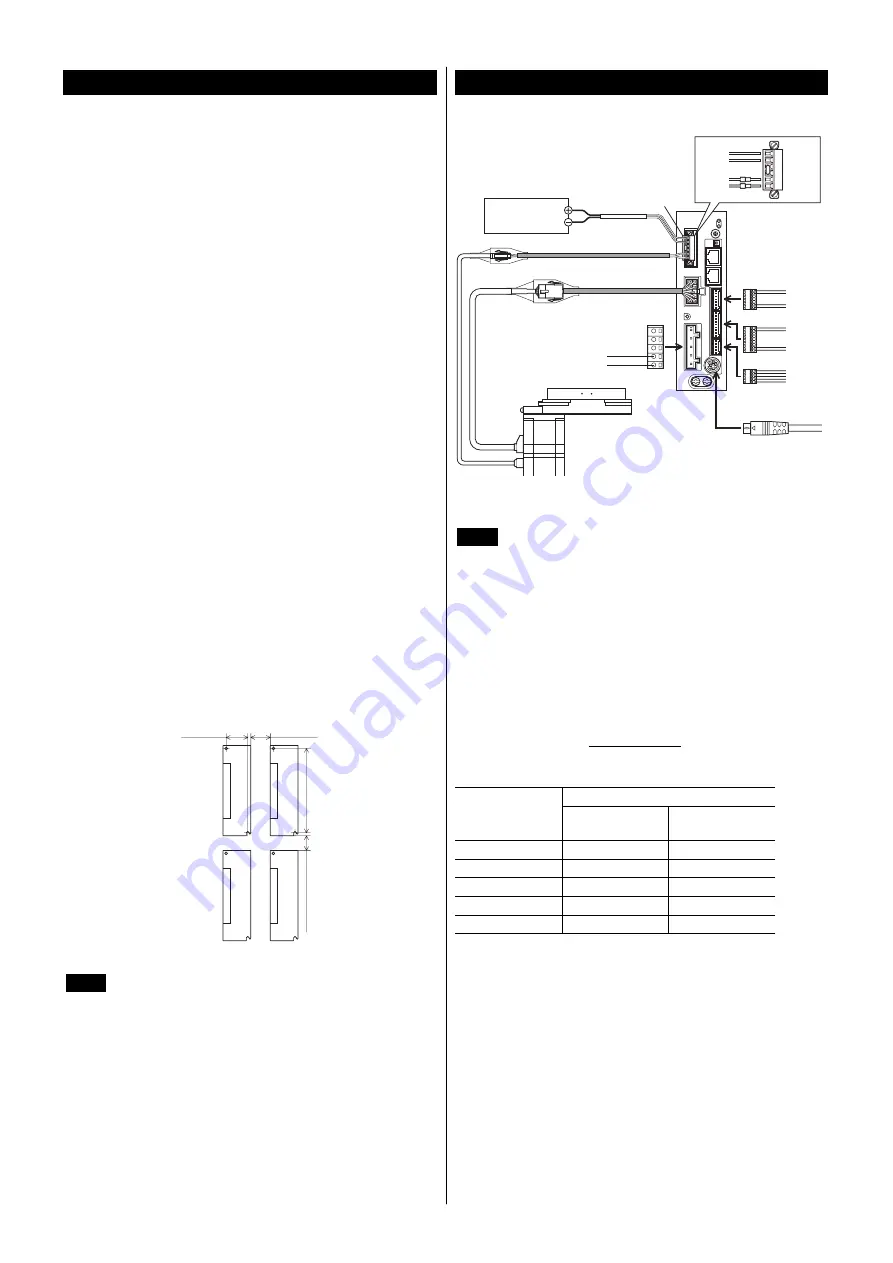
be installed side by side, provide 20 mm (0.79 in.) and 25 mm (0.98
in.) clearances in the horizontal and vertical directions, respectively.
When installing the driver in an enclosure, use two screws (M4; not
supplied) to secure the driver through the mounting holes.
20 (0.79)
or more
150 (5.91)
25 (0.98) or more
35 (1.38)
Unit: mm (in.)
Note
•
Install the driver in an enclosure whose pollution
degree is 2 or better environment, or whose degree of
protection is IP54 minimum.
•
Do not install any equipment that generates a large
amount of heat or noise near the driver.
•
Do not install the driver underneath the controller or
other equipment vulnerable to heat.
•
If the ambient temperature of the driver exceeds
55 °C (131 °F), improve the ventilation condition.
•
Be sure to install the driver vertically (vertical
position).
Connection
Connection example
Cable for motor
Cable for electromagnetic brake
CN1 connector
24 VDC±5%
0.75 A or more
24 VDC power supply
CN1
Output
signals
Input
signals
Sensor
signals
∗
2
∗
2
∗
2
•
•
•
•
•
•
CN2
CN3
CN5
CN8
CN9
Main power supply
Single-phase 100-120 V
or
Single-phase 200-240 V
∗
1
CN4
䋺
OPX-2A
or
MEXE02
∗
3
Black
-
+
White
MB1
MB2
24 V+
24 V-
∗1
Lead wire for main power supply: AWG16 to 14 (1.25 to 2.0 mm
2
)
∗2
Lead wire for I/O signals: AWG26 to 20 (0.14 to 0.5 mm
2
)
∗3
Lead wire for CN1: AWG28 to 16 (0.08 to 1.25 mm
2
)
Note
•
Have the connector plugged in securely. Insecure
connections may cause malfunction or damage to the
actuator or driver.
•
Do not wire the power supply cable of the driver in the
same cable duct with other power lines or motor
cables. Doing so may cause malfunction due to
noise.
•
When cycling the power or plugging/unplugging the
connector, turn off the power and wait for the
CHARGE LED to turn off. Residual voltage may
cause electric shock.
•
When installing the actuator to a moving part, use an
accessory flexible cable offering excellent flexibility.
Refer to the USER MANUAL for details.
Power supply current capacity
Power supply current capacity
Model
Single-phase
100-120 V
Single-phase
200-240 V
DG85
2.4 A or more
1.5 A or more
DG130
3.6 A or more
2.3 A or more
DG200
5.9 A or more
3.7 A or more
EAS4
2.4 A or more
1.5 A or more
EAS6
3.6 A or more
2.3 A or more


