Speed Contr
ol S
y
st
ems
B-152
ORIENTAL MOTOR GENERAL CATALOG
2009/2010
Features B-138
/
System Configuration B-139
/
Product Line B-140
/
Specifications B-141
Connecting the Motor and Speed Controller
◇
A motor cable is not supplied with the product. Please purchase the appropriate cable.
●
Connecting the Motor
[Applicable lead wires]
AWG18 (0.75 mm
2
) min.
[Applicable Crimp Terminals]
Use a crimp terminal for the electromagnetic brake type.
•
Terminal Block
Round Terminal with Insulation
U-Shape Terminal with Insulation
ϕ
3.6 mm (
0.14
in.) min.
3.8 mm
(
0.15
in.) max.
7.2 mm (
0.28
in.) max.
after crimp
6.2 mm (
0.24
in.) max.
after crimp
6.2 mm (
0.24
in.) max.
6.2 mm (
0.24
in.) max.
3.6 mm (
0.14
in.) min.
•Protective Earth Terminal
Round Terminal with Insulation
ϕ
4.1 mm (
0.16
in.) min.
4.8 mm
(
0.19
in.) max.
9.5 mm (
0.37
in.) max.
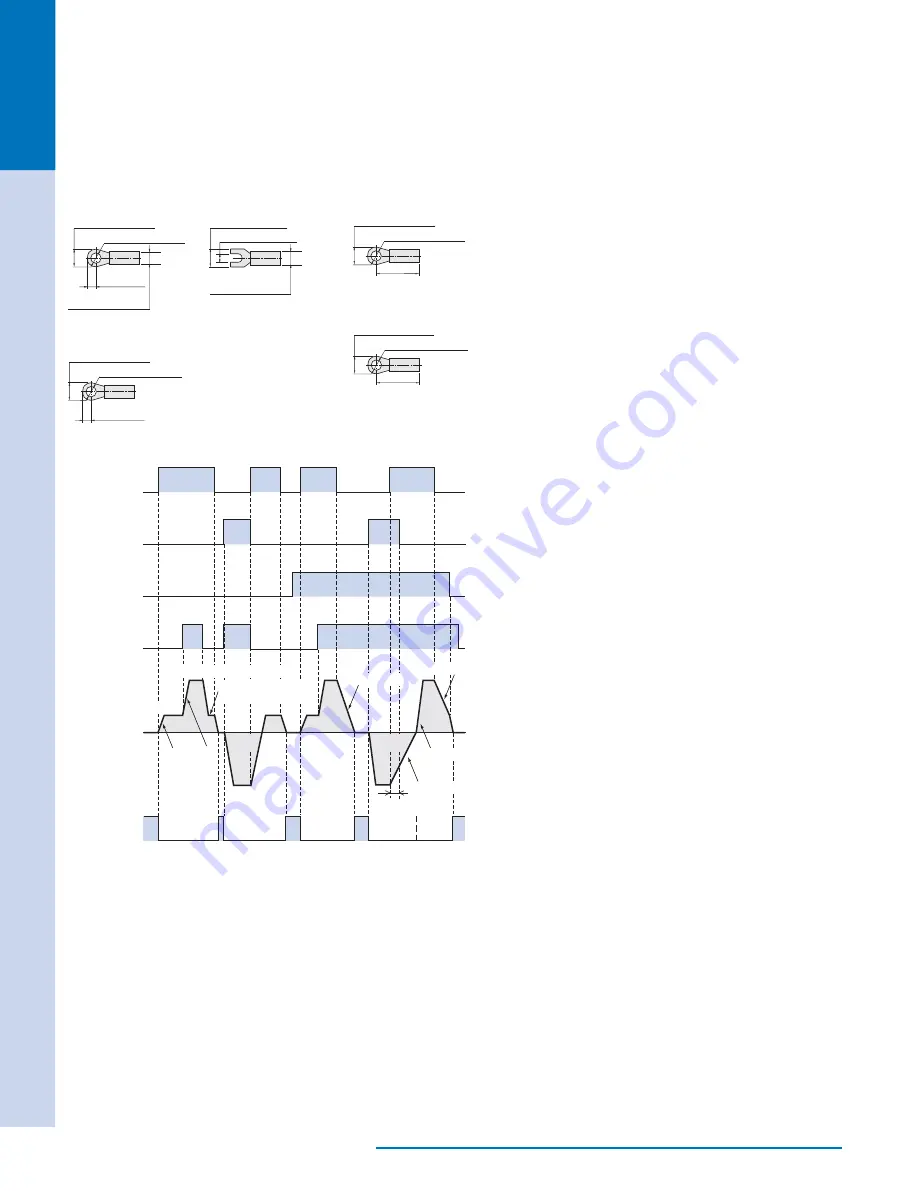
Timing Chart
●
500 r/min
(Internal potentiometer)
CW input
CCW input
SD input
MO input
Motor operation
Electromagnetic
Brake
ON
OFF
ON
OFF
ON
OFF
ON
OFF
Release
Release
Release
Release
Release
CW
CW
CW
CW
CCW
CCW
1500 r/min (External potentiometer)
500 r/min
(Internal potentiometer)
Acceleration
Acceleration
Deceleration
✽
1
✽
2
Deceleration
Deceleration
1
✽
The motor will stop if the CW and CCW inputs are simultaneously turned to ON.
2
✽
The electromagnetic brake may be left released when the motor runs and/or stops in
a short cycle or a shorter time is set for the acceleration/deceleration time.
The CW input signal, CCW input signal, M0 input signal
●
and SD input signal can be used to control all motor
operations, such as run, stop, direction switching, speed
switching.
Switching the CW input ON will cause the motor to
●
turn clockwise as viewed from the motor shaft, while
switching the CCW input ON will cause the motor to turn
counterclockwise. Switching each signal OFF will stop the
motor. The motor will start at the rise time corresponding to
the time set on the acceleration time potentiometer.
Switching the M0 input ON select the speed set on the
●
external speed potentiometer. Switching the M0 input OFF
will cause the motor to operate at the speed set on the
internal speed potentiometer. The timing chart shown left is
based on an internal speed potentiometer setting of
500 r/min and an external speed potentiometer setting of
1500 r/min.
If the motor is stopped with switching the SD input ON,
●
the motor stops at the time set by the deceleration time
potentiometer.
To release the electromagnetic brake when the motor is
●
stopped, turn the FREE (electromagnetic brake release)
input ON. This releases the electromagnetic brake and
allow the motor’s output shaft to turn freely. (This function
is available only with a speed control system with an
electromagnetic brake.)
Note:
Ensure that the temperature of the motor case does not exceed 90˚C (194˚F).
●
●
Connecting the Speed Controller
[Applicable lead wires]
AWG18 (0.75 mm
2
) min.
[Applicable Crimp Terminals]
•
Power Connection Terminal,
Motor Connection Terminal
Round Terminal with Insulation
ϕ
3.2 mm (
0.13
in.) min.
9 mm
(
0.35
in.) min.
6.2 mm (
0.24
in.) max.
•Protective Earth Terminal
Round Terminal with Insulation
ϕ
4.3 mm (
0.17
in.) min.
17 mm
(
0.67
in.) min.
8.5 mm (
0.33
in.) max.
Input/Output Signal Terminals
When a crimp terminal is used for connection,
use such terminals as shown below.
Manufacturer: Phoenix Contact
AI
0.25-6
Applicable wire size: AWG24 (0.2 mm
2
)
AI
0.34-6
Applicable wire size: AWG22 (0.3 mm
2
)
AI
0.5-6
Applicable wire size: AWG20 (0.5 mm
2
)


