2
Precautions for use
This section covers restrictions and requirements the user should consider when using the
product.
Be sure to match the motor output power with the driver output power.
Wiring
z
Connecting the motor and driver
To connect the motor and driver, always use the dedicated connection cable (sold
separately).
z
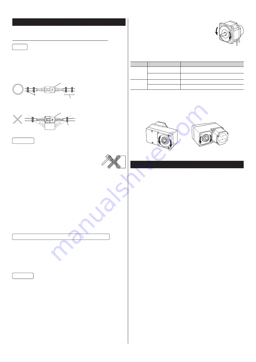
How to fix the cable
Fix the cable at the positions near the connector so that no stress is applied on the
connector part.
A wide clamp is also available to use
When the cable is moved, it
causes the connectors to move,
causing stress to apply on the
connector part.
Fix using two banding bands
or a wide clamp.
•
Fixing at one place on each side
•
Fixing at two places on each side
Connector
Connector
Banding band, etc.
Banding band, etc.
When installing the motor on a moving part, use a flexible cable offering excellent flexibility.
Installation
z
Make sure not to hit or apply a strong impact on the motor output shaft or
the encoder.
Applying a strong impact on the motor output shaft or the encoder
may cause encoder damage or motor malfunction.
z
Grease measures
On rare occasions, grease may ooze out from the gearhead. If there is concern over
possible environmental damage resulting from the leakage of grease, check for grease
stains during regular inspections. Alternatively, install an oil pan or other device to prevent
damage resulting from contamination. Grease leakage may lead to problems in the user’s
equipment or products.
z
When using in low temperature environment
When an ambient temperature is low, a load torque may increase due to the oil seal
or viscosity of grease used in the gearhead, and the output torque may decrease or
an overload alarm may be generated. However, as time passes, the oil seal or grease is
warmed up, and the motor can be operated without generating the overload alarm.
z
Apply grease to the hollow output shaft of a hollow shaft flat gearhead.
When using a hollow shaft flat gearhead, apply grease (molybdenum disulfide grease,
etc.) on the surface of the load shaft and inner walls of the hollow output shaft to prevent
seizure.
Insulation resistance measurement and dielectric strength test
z
Do not conduct the insulation resistance measurement or the dielectric
strength test with the motor and driver connected
Conducting the insulation resistance measurement or the dielectric strength test with the
motor and driver connected may result in damage to the product.
z
Do not conduct the insulation resistance measurement or dielectric strength
test on an encoder.
Doing so may damage the product.
Operations
z
Use an electromagnetic brake motor in an application of vertical drive such
as elevating equipment.
When the motor is used in an application of vertical drive such as elevating equipment
(lifting and lowering device), use an electromagnetic brake motor so that the load can be
held in position.
z
Rotation direction
The rotation direction of the motor output shaft can
be changed by setting of the “Motor rotation direction”
parameter.
The figure shows an example when the parameter is the
initial value.
RVS input
FWD input
•
Combination type-parallel shaft gearhead
The rotation direction of the gearhead output shaft may vary with that of the motor output
shaft depending on the gear ratio of the gearhead.
Model
Gear Ratio
Rotation direction of the gearhead output shaft
BXM230
BXM460
BXM5120
5
,
10
,
15
,
20
,
200
Same direction as the motor
30
,
50
,
100
Opposite direction to the motor
BXM6200
BXM6400
5
,
10
,
15
,
20
,
100
,
200
Same direction as the motor
30
,
50
Opposite direction to the motor
•
Combination type-hollow shaft flat gearhead
At all gear ratios, the output shaft rotates in the opposite direction to the motor as viewed
from the gearhead front side.
The rotation direction is different depending on whether the pre-assembled motor/
gearhead is viewed from the front side or rear side.
Check with the figure below.
Viewed from front side
Viewed from rear side
FWD input
RVS input
FWD input
RVS input
Checking the product
This section explains the items you should check, as well as the name of each part.
Package contents
Verify that the items listed below are included. Report any missing or damaged items to
the branch or sales office from which you purchased the product.
z
Combination type-parallel shaft gearhead
Motor ...............................................................1 unit (a gearhead is pre-assembled)
Mounting screw ...........................................1 set
(hexagonal socket head screw, plain washer, spring washer, nut each 4 pcs,
parallel key 1 pc
*
)
Operating manual (this document) ......1 copy
*
For the 200 W and 400 W types, the parallel key is fixed to the gearhead output shaft.
z
Combination type-hollow shaft flat gearhead
Motor ...............................................................1 unit (a gearhead is pre-assembled)
Mounting screw ...........................................1 set
(hexagonal socket head screw, plain washer, spring washer, nut
*
each 4 pcs,
parallel key 1 pc)
Safety cover ...................................................1 set
(safety cover 1 pc, mounting screw for safety cover 2 pcs)
Operating manual (this document) ......1 copy
*
For the 200 W and 400 W types, nuts are not included.
z
Round shaft type
Motor ...............................................................1 unit
Operating manual (this document) ......1 copy


