Operating instructions BRB
9 Clamping wedge and mandrel assembly BRB 4
orbitalum tools
gmbh
(08.10)
MT_BRB_BA_04_790086762_00.doc
57
9.5.4
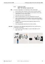
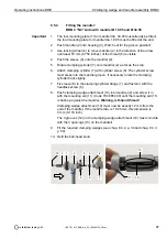
Fitting the mandrel:
BRB 4 "NC" Auto with mandrel Ø 19.05 and Ø 34.50
1. The tool mounting plate (1) for mandrel dia. 34.05 must already be fitted;
the tool mounting plate for mandrel dia. 19.05 must be fitted at the end.
2. Push mandrel (2) into housing (3). Watch out for the groove position!
3. Use locking wheel (4) to move mandrel (2) in the direction of the arrow
until least 70 mm (2.756 inches) of the thread (5) is visible.
4. Push the sleeve (6) onto the mandrel (2).
5. Rotate clamping cylinder (7) onto mandrel (2) as far as the stop.
6. Attach clamping cylinder (7) with cylinder screw (8). The cylinder screw
must press into the mandrel groove, if necessary rotate the clamping
cylinder back slightly.
7. Fix sleeve (6) to the clamping cylinder flange (7) and fasten it with the
headless screw (9).
8. Push clamping wedge attachment (10) into mandrel (2) and screw it in
with the mounting aid (11) (Code 790 085 490) until the mounting aid (11)
is flush up against the mandrel.
Warning, left-hand thread!
Clamping wedge attachment (10) must now be exactly 12 mm from the
end of the mandrel. If the mandrel dia. is 19.05 mm, this dimension is
3 mm (0.118 inch)
The 3 grooves (12) on the clamping wedge attachment (10) must coincide
with the 3 openings (13) on the mandrel!
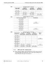
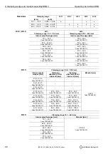
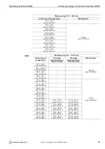
9. Fit the required clamping wedges (see chap. 8.3.2, p. 34 and chap. 9.3.3,
p. 50).
10. Refit the ball-head knob.
Important
4
7
1
3
9
5
12
11
8
6
10 2
13

