Operating instructions BRB
8 Clamping wedge and mandrel assembly BRB 2
orbitalum tools
gmbh
(08.10)
MT_BRB_BA_04_790086762_00.doc
37
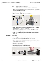
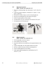
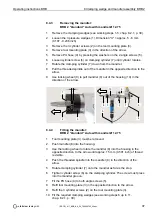
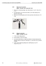
8.4.3
Removing the mandrel:
BRB 2 "standard" Auto with mandrel Ø 12.75
1. Remove the clamping wedges (see working steps 1-5, chap. 8.2.1, p. 30).
2. Loosen the 3 pressure wedges (1). Dimension "X" = approx. 5 - 6 mm
(0.197 - 0.236 inch).
3. Remove the 3 cylinder screws (2) on the tool mounting plate (3).
4. Remove tool mounting plate (3) in the direction of the arrow.
5. Remove PU hose (4) by pressing the washers on the 2 angle screws (5).
6. Loosen cylinder screw (6) on clamping cylinder (7) until cylinder rotates.
7. Rotate the clamping cylinder (7) down from the mandrel.
8. Pull the threaded spindle out of the mandrel in the opposite direction to the
arrow.
9. Use locking wheel (9) to pull mandrel (8) out of the housing (10) in the
direction of the arrow.
8.4.4
Fitting the mandrel:
BRB 2 "standard" Auto with mandrel Ø 12.75
1. Tool mounting plate (3) must be removed.
2. Push mandrel (8) into the housing.
3. Use the locking wheel to rotate the mandrel (8) into the housing in the
opposite direction to the arrow until approx. 15 mm (0.591 inch) of thread
is visible.
4. Push the threaded spindle into the mandrel (8) in the direction of the
arrow.
5. Rotate clamping cylinder (7) onto the mandrel as far as the stop.
6. Tighten cylinder screw (6) on the clamping cylinder. The screw must press
into the mandrel groove.
7. Fit the PU hose (4) to both angle screws (5).
8. Refit tool mounting plate (3) in the opposite direction to the arrow.
9. Refit the 3 cylinder screws (2) on the tool mounting plate (3).
10. Fit the required clamping wedges (see working steps 6 up to 11,
chap. 8.2.1, p. 30).
3
X
1
2
3
8
10
9
6
5
7
4
5


