


3-24
Installing and Operating the Tablet and Base Station E-Series
4.
Route the cable to either side of the I/O Panel. Each footer contains a slot to route the
interface cable. Remove the appropriate rear foot, place the cable in the slot, and then
reinstall the foot.
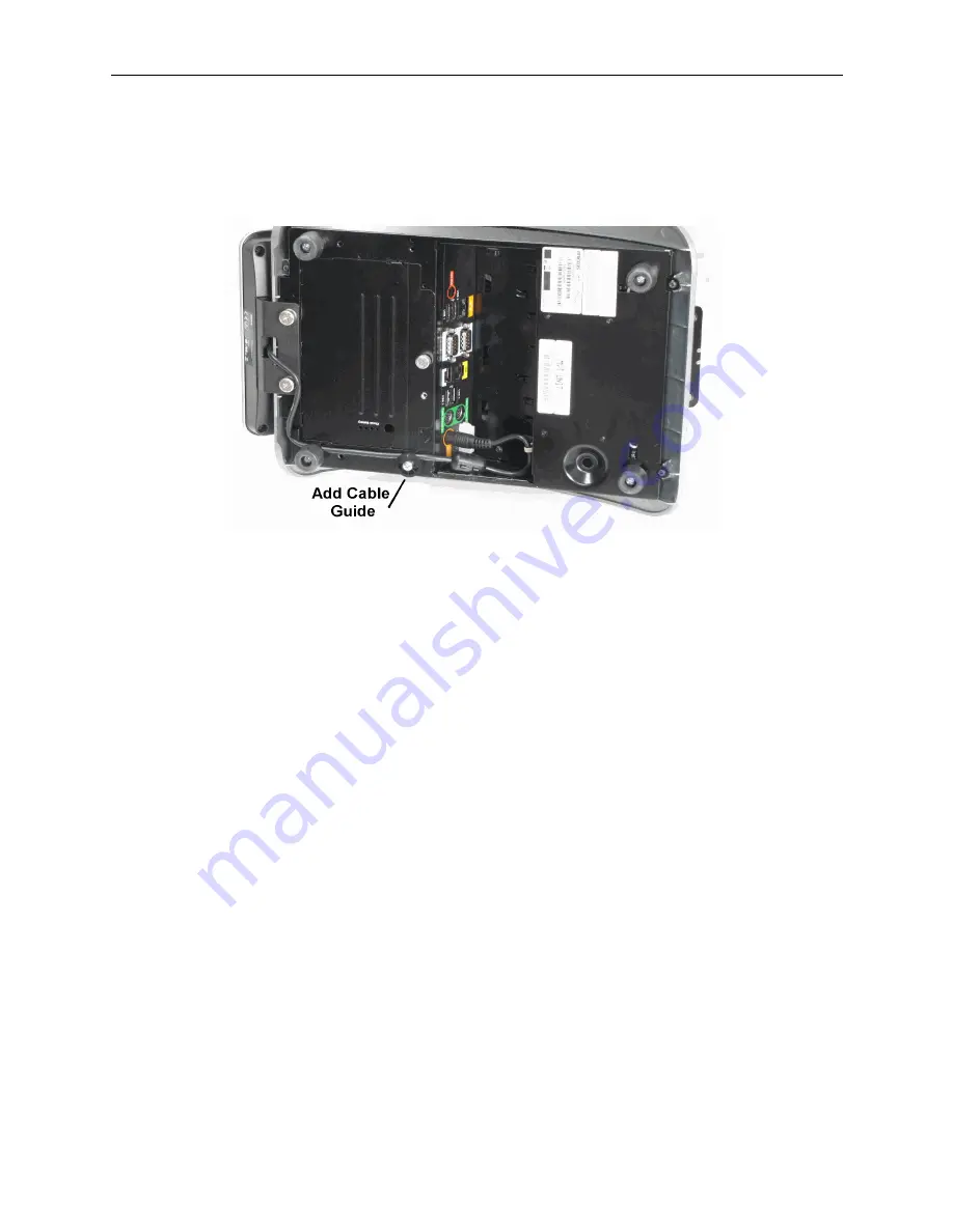
5.
Add the cable guide and screw supplied in the kit to keep the cable secure to the
chassis.
Figure 3-25 Installing the Cable Guide
6.
Attach the keyed 4-pin mini-DIN to the I/O panel connector marked Customer
Display.
Installing the MICROS Integrated Mini Printer
This section describes how to install the Integrated Mini Printer on the Base Station R-
Series or E-Series.
The Integrated Mini Printer can only be installed on the right side of the Base Station
chassis. Do not connect the Mini Printer to the Base Station when it is powered on.
1.
Before installing, remove the Tablet, AC power cable, and optional battery, if
installed.
2.
Attach the Printer Bracket so that it is flush with the edge of the I/O Panel and facing
the rear of the Base Station.
3.
Connect the Mini Printer to COM2. 12V is enabled by default.
4.
Attach the Mini Printer Bracket to the Ventilation Slot.
Содержание e-series
Страница 1: ...Oracle MICROS Tablet and Base Station E Series Setup Guide November 2015...
Страница 10: ......
Страница 36: ......
Страница 64: ......
Страница 70: ...A 2 Appendix A MICROS Tablet E Series 11...
Страница 71: ...Appendix A A 3 MICROS Tablet and Base Station E Series...
Страница 72: ...A 4 Appendix A MICROS Tablet and Base Station E Series with Integrated LCD Customer Display...
Страница 73: ...Appendix A A 5 MICROS Tablet and Base Station E Series LCD Customer Pole Display...
Страница 74: ...A 6 Appendix A MICROS Tablet and Base Station E Series with Integrated Mini Printer...
Страница 75: ...Appendix A A 7 MICROS Tablet and Base E Series with Integrated Scanner...
Страница 76: ...A 8 Appendix A MICROS Tablet Multi Unit Charger Surface Mount...
Страница 77: ...Appendix A A 9 MICROS Tablet Multi Unit Charger Wall Mount...
Страница 78: ......


