background image

8

Gather pairs, trim and carefully

insert into RJ45 plug:

Crimp wires in place using a

professional quality crimping tool

to ensure a secure connection: 

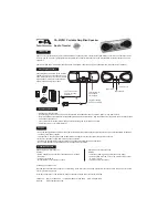
1. Using a single Cat5e cable, connect the AMR650-A to the

MCU300 via an RJ45 plug at the Master Control Unit, and the 8-
way colour-coded punch down connection at the AMR650-A.

The RJ45 hub connection should be wired to EIA/TIA568A
standard as shown.
The Cat5 connection from MCU to the AMR650-A should not
exceed 30 metres/100 feet.

2. The AMR650-A is then connected to the AMR650-P using either

Cat5e cable terminated at 8-way colour-coded punch down
connections (all 8 cores must be connected) or using a run of
standard speaker cable. 

Only one method of connection between the active and passive
speaker is necessary.

Note: Use a professional quality punch down tool to ensure secure

punch down connections.

CONNECTING THE AMR650 V2.0

EIA / TIA 568A wiring standard

(view from contact end):

1 white/green

2 green

3 white/orange

4 blue

5 white/blue

6 orange

7 white/brown

8 brown

1

2 3 4 5 6 7 8

Cat5e cable terminated at AMR650

V2.0 8-way punch down connector:

1 white/brown

2 brown

3 white/blue

4 blue

5 white/green

6 green

7 white/orange

8 orange

MCU300

AMR650-P

Cat5/5e

AMR650-A

Cat5/5e (or standard

loud-speaker cable)

PSA65U

Содержание AMR650 V2.0

Страница 1: ...AMR650 V2 0 A BUS Active Ceiling Speakers Installation Guide...

Страница 2: ...650 V2 0 12 Sound adjustment functions 13 Technical specifications 14 Limited warranty 15 CONTENTS This package should contain the following 1 x AMR650 A V2 0 Active Speaker 1 x AMR650 P V2 0 Passive...

Страница 3: ...ide fully as it contains important information and should be retained for future reference 3 INTRODUCTION AMR650 A AMR650 P Your speakers are an example of superior design and craftsmanship These sugg...

Страница 4: ...ing the AMR650 V2 0 speakers thought should be given to positions which give the best desired sound coverage throughout a room while not interfering with existing or planned light fittings or joists A...

Страница 5: ...eaker surround to avoid getting paint getting on the speaker cone 3 Spray painting the grille will prevent blocking the grille holes with paint For the AMR650 A unscrew the IR window assembly before s...

Страница 6: ...tereo Mono jumper CN17 4 Local input 5 Preamp output 6 Stereo Mono jumper CN14 7 Cat 5e connection to passive speaker 8 Speaker cable connection to passive speaker 9 123 jumper no current function 10...

Страница 7: ...MR650 V2 0 onboard option See page 10 for further details Opus A BUS Swtiches between Opus Enhanced mode for use with Octopus hubs and normal A BUS mode For use with an Octopus MCU300 A BUS hub the ju...

Страница 8: ...g either Cat5e cable terminated at 8 way colour coded punch down connections all 8 cores must be connected or using a run of standard speaker cable Only one method of connection between the active and...

Страница 9: ...ch red dog leg foot to the LEFT into it s holding slot and then insert the speaker into the mounting hole 3 Using a cross head screwdriver slowly turn each fixing screw clockwise This will move the mo...

Страница 10: ...efault jumper positions on the AMR650 A move the CN17 jumper to the LEFT end pins and the CN14 jumper stays on the RIGHT end pins see page 7 10 Local Source Input It is possible to install a piece of...

Страница 11: ...ive output levels between the AMR650 V2 0 and the auxilary component Move the Fader jumper switch on the AMR650 A to the the centre and right pins see page 7 Independent 24V local power supply The AMR...

Страница 12: ...ource on the VSU300 if fitted 3 All off Switches the whole system to Standby 4 Mute Mutes the audio output of the room 5 Standby Switches the whole system to Standby mode Audio is muted and 12 V trigg...

Страница 13: ...t range has been reached Adjust the balance using the Volume buttons Up towards right Down towards left Bass Fader if applicable Press the Select button once One bleep will sound Press the Select butt...

Страница 14: ...wever no guarantee is given to the correctness of the contents The information in this document is subject to change without notice If you notice any errors please feel free to email us at info opus t...

Страница 15: ...o confirm that you have an unaltered serial number and or you purchased from a Opus Technologies authorised dealer This Warranty does not cover cosmetic damage or damage due to acts of God accident mi...

Страница 16: ...Opus is committed to providing the highest levels of service and support For full details of this product visit the Opus website www opus technologies co uk Part No AP18922 1...

Отзывы: