2: QUICK START
SNAP-LCM4 User’s Guide
8
INSTRUCTIONS
1.
Unpack the controller. Check to make sure you have the following:
–
SNAP-LCM4 controller
–
jumpers
–
connectors
–
3.6-V lithium backup battery
–
floppy disk containing firmware.
2.
With the power supply off or unplugged, connect it to the controller.
The SNAP-LCM4 controller requires only 5 VDC power, which can be supplied by the Opto 22 SNAP-PS5
or any 5 V power supply meeting SNAP-LCM4 power requirements.
The controller does not have a power switch; to turn it off, switch off the power supply.
CAUTION
Reversing wire polarity may cause damage to your controller. This damage is not covered by Opto 22’s
warranty. If in doubt about which wire is which on your power supply, check with a meter.
a.
With the power supply off or unplugged, connect the +5 V lead from the power supply (normally
red) to the +5V terminal on the SNAP-LCM4 backplane.
b.
Connect the COM wire from the power supply (normally black) to the GND terminal on the
SNAP-LCM4 backplane. Optionally, you can connect the earth ground terminal to panel ground.
3.
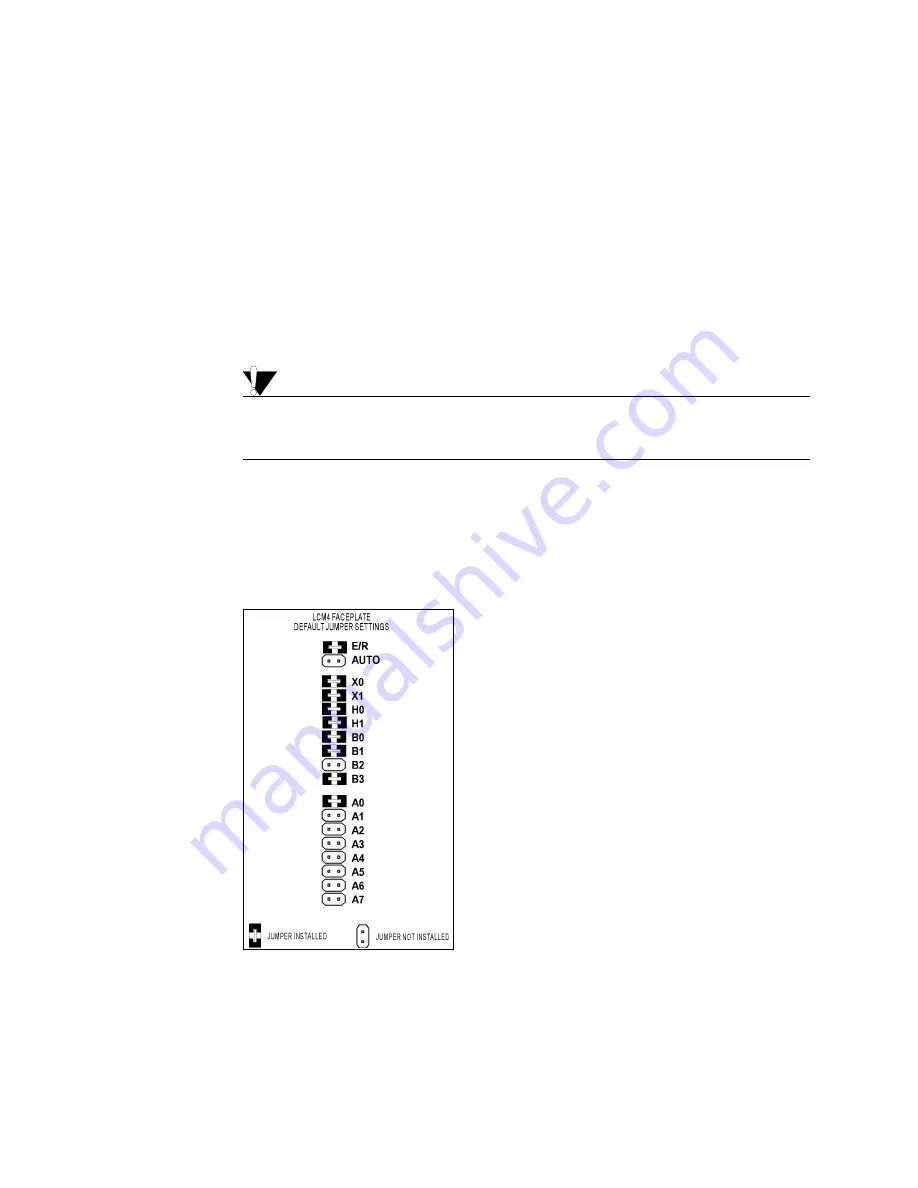
If necessary, change the configuration jumpers.
Default jumper settings are as follows:
If you are not using factory defaults, see Chapter 3 to change the jumpers.
4.
If necessary, install optional adapter cards.
See the data sheet for the adapter card for complete installation instructions.
Default Jumper Settings
EEPROM/RAM:
Run from RAM
Autoboot:
Disabled
Communication:
Binary
BootLoader:
Boot to kernel
Host port:
COM 0
Baud rate:
38.4 K
Address:
1


