


USER MANUAL
DVI MATRIX ROUTER : ODM-88
ODM-88 Manual
Page 29
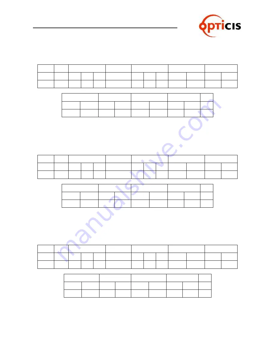
1) Output Channel 1
Input Channel 1, Output Channel 2
Input Channel 2, Output Channel 3
Input
Channel 3
Byte
Start
Router ID
Command
Data Length
Output Channel Input Channel
ASCII
*
2
5
5
4
0
1
2
0
1
0
1
Hex
2Ah
32h 35h 35h
34h
30h 31h 32h
30h
31h
30h
31h
Output Channel Input Channel Output Channel Input Channel End
0
2
0
2
0
3
0
3
!
30h
32h
30h
32h
30h
33h
30h
33h
21h
2) Output Channel 1
Input Channel 2, Output Channel 2
Input Channel 3, Output Channel 3
Input
Channel 1
Byte
Start
Router ID
Command
Data Length
Output Channel Input Channel
ASCII
*
2
5
5
4
0
1
2
0
1
0
2
Hex
2Ah
32h 35h 35h
34h
30h 31h 32h
30h
31h
30h
32h
Output Channel Input Channel Output Channel Input Channel End
0
2
0
3
0
3
0
1
!
30h
32h
30h
33h
30h
33h
30h
31h
21h
3) Output Channel 1
Input Channel 3, Output Channel 2
Input Channel 1, Output Channel 3
Input
Channel 2
Byte
Start
Router ID
Command
Data Length
Output Channel Input Channel
ASCII
*
2
5
5
4
0
1
2
0
1
0
3
Hex
2Ah
32h 35h 35h
34h
30h 31h 32h
30h
31h
30h
33h
Output channel Input channel Output channel Input channel End
0
2
0
1
0
3
0
2
!
30h
32h
30h
31h
30h
33h
30h
32h
21h
Содержание ODM- 88
Страница 1: ...Edition 2A ODM 88 DVI Matrix Router USER MANUAL ...
Страница 2: ...USER MANUAL DVI MATRIX ROUTER ODM 88 ODM 88 Manual Page 2 ...
Страница 3: ...USER MANUAL DVI MATRIX ROUTER ODM 88 ODM 88 Manual Page 3 ...
Страница 51: ...USER MANUAL DVI MATRIX ROUTER ODM 88 ODM 88 Manual Page 51 3 4 5 Title Folder Initial screen of PC Software ...


