22
280ES / 420ES / 650ES / 1000ES / 1400ES
PIN7
Common for pin 6 and pin 9.
PIN8
Not connected
PIN9
RS232 transmitter pin (
TXD
).
Note:
1. Pin 2 and pin 5 are open collector outputs which must be pulled up to a common
referenced supply, switch rating: +40V, 0.15A non-inductive.
2. Pin 4 and pin 7 should
only
be connected to ground.
2.8 Data-Line Surge Suppression
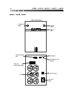
The data-line surge suppression on the rear panel provides an easy way to protect a
network (
RJ45
) or modem (
RJ11
) connection from hazardous spikes. Connect your
10/Base-T network cable or a single line telephone cable to the “Line” socket. To
complete the connection, connect another network cable or telephone line cable from the
“System” socket to your computer. The network cable and telephone line are optional
accessories, which may be purchased from your local dealer.


