301 Fulling Mill Road, Suite G ©Copyright 2004 by OnQ Technologies,
Middletown, PA 17057
Inc All Rights Reserved.
(800) 321-2343
www.onqhome.com
(
)
4
Innovations in Home Living.
D. On-Q Home 4 Port Router/Switch Detailed Physical Description
The following information describes the physical characteristics of the
On-Q Home Router/Switch:
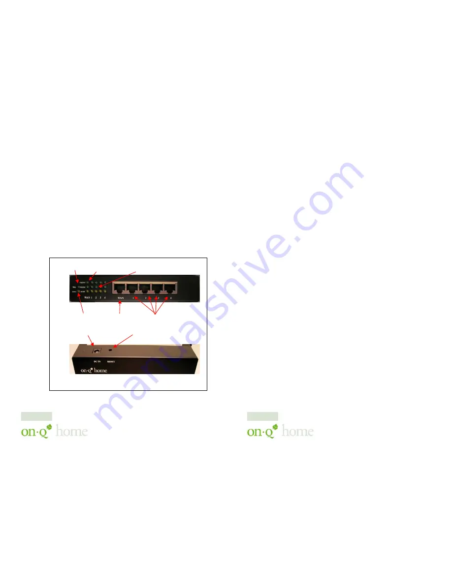
1. Router/Switch Module Connection Area
Figure 2
shows the Router/Switch connection area including:
DC Input connector – connection from power supply
WAN (Internet) Port – 8 position RJ-45 jack (connects to Cable or
DSL modem)
Local Switch Ports – 8 position RJ-45 jacks (connection from outlets
in rooms)
Reset Button -
A button press (over 3 seconds) resets the
Router/Switch unit to the factory default settings. This clears all user
settings, including User Name, Password, IP Address, and Subnet
Mask.
NOTE: Refer to
Section IV
Configuration
for instructions on re-
configuring the Router/Switch.
Figure 2
Diag LED
Switch Port LEDs
WAN LEDs
STATUS
Power LED
DC Input
Reset Button
WAN Port
Local Switch Ports
Page 3
301 Fulling Mill Road, Suite G ©Copyright 2004 by OnQ Technologies,
Middletown, PA 17057
Inc All Rights Reserved.
(800) 321-2343
www.onqhome.com
(
)
4
Innovations in Home Living.
2. Router/Switch Status LEDs (see
Figure 2
)
Power
– On solid orange when power is supplied.
Diag
– On solid green indicates router’s self-diagnosis mode is
running during boot-up/restart.
10/100 Local Port and WAN Port LEDs
Link/Act
– On solid green indicates functional network link
through the port with the attached device. Blinking green
indicates router is sending/receiving data over that port.
Fdx/Col
– On solid green indicates the connection through the
port is running in Full Duplex Mode. Blinking green indicates
connection is experiencing collisions.
100/10
– On solid orange indicates port is operating at 100
Mbps. Off indicates 10 Mbps.
Page 4


