


(1) Use G9SX-SM
within an enclosure with IP54 protection or higher
according to IEC/EN60529. Be sure to connect the enclosure to earth(PE).
(2) Incorrect wiring may lead to loss of safety function. Wire conductors
correctly and verify the operation of G9SX-SM
before using the system
in which G9SX-SM
is incorporated.
(3) Do not apply DC voltages exceeding the rated voltages, nor any AC
voltages to G9SX-SM
. Do not connect to DC distribution network.
(4) Use DC supply satisfying requirements below to prevent electric shock.
- DC power supply with double or reinforced insulation, for example,
according to IEC/EN60950 or EN50178 or a transformer according to
IEC/EN61558.
- DC supply satisfies the requirement for class 2 circuits or limited
voltage/current circuit stated in UL 508.
(5) Apply properly specified voltages to G9SX-SM
inputs.
Applying inappropriate voltages cause G9SX-SM
to fail to perform its
specified function, which leads to the loss of safety functions or damages
to G9SX-SM
.
(6) Auxiliary error outputs and auxiliary monitoring outputs are NOT safety
outputs.
Do not use auxiliary outputs as any safety output.
Such incorrect use causes loss of safety function of G9SX-SM
and its
relevant system.
(7) After installation of G9SX-SM
, qualified personnel should confirm the
installation, and should conduct test operations and maintenance.
The qualified personnel should be qualified and authorized to secure the
safety on each phases of design, installation, running, maintenance and
disposal of system.
(8) A person in charge, who is familiar to the machine in which G9SX-SM
is
to be installed, should conduct and verify the installation.
(9) G9SX-SM
determines that motor stops when the standstill detection
input voltage is predetermined value or less. According to the
characteristic or load condition of motor, it may turn on safety detection
outputs before motor stops completely. In that case, before operation, the
qualified personnel should verify that risk of the rotation condition after
output is acceptable.
(10) Perform daily and 6-month inspections for the G9SX-SM
. Otherwise,
the system may fail to work properly, resulting in serious injury.
(11) Do not dismantle, repair, or modify G9SX-SM
. It may lead to loss of its
safety functions.
(12) Use only appropriate components or devices complying with relevant
safety standards corresponding to the required level of safety categories.
Conformity to requirements of safety category is determined as an entire
system.
It is recommended to consult a certification body regarding assessment
of conformity to the required safety level.
(13) OMRON shall not be responsible for conformity with any safety
standards regarding to customer's entire system.
(14) Disconnect G9SX-SM
from power supply when wiring. Devices
connected to G9SX-SM
may operate unexpectedly.
(15) Be cautious not to have your fingers caught when attaching terminal
sockets to the plugs on G9SX-SM
.
(16) Do not use in combustible gases or explosive gases.
(17) Driving voltage of the motor is impressed to the standstill detection
inputs. Connect overcurrent protective equipment; fuse, circuit-breaker
etc., (3A Max.) and tighten the wirings by rated tightening torque to the
standstill detection inputs.
Precautions for Safe Use
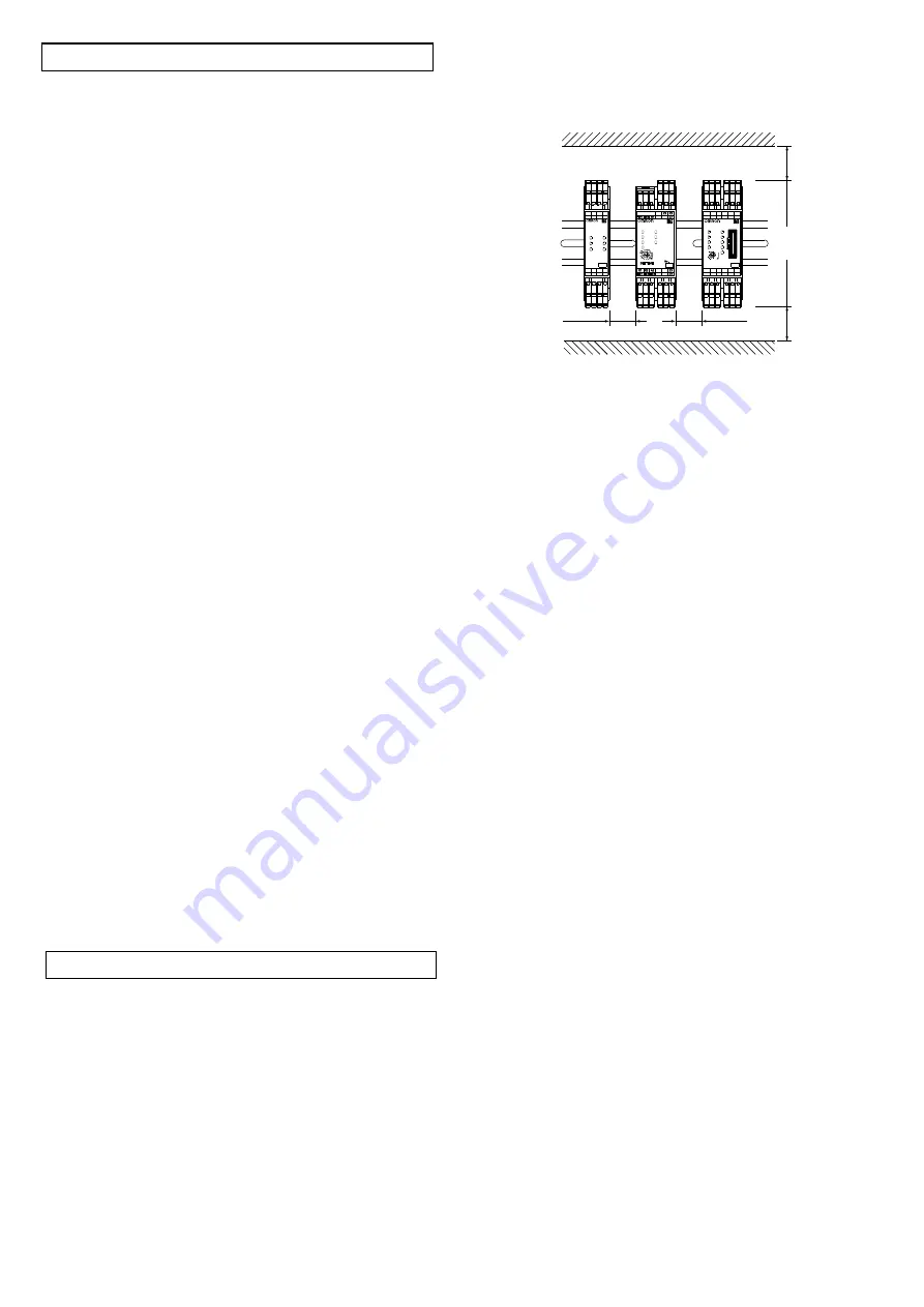
(4) Following spacing around G9SX should be available to apply rated
current to outputs of G9SX and for enough ventilation and wiring:
1) At least 25 mm beside side faces of G9SX.
2) At least 50 mm above top face of G9SX and below bottom face
of G9SX.
(5) Wiring
1) For model G9SX-SM
Use the following to wire to G9SX-SM
.
-Solid wire: 0.2 to 2.5mm
2
AWG24 to AWG12
-Stranded wire (Flexible wire): 0.2 to 2.5mm
2
AWG24 to AWG12
Strip the cover of wire no longer than 7mm.
2) For model G9SX-SM
-RT (with screw terminals)
Tighten each screw with a specified torque of 0.5 to 0.6N
m, or
the G9SX-SM
may malfunction or generate heat.
(6) Use cables with length less than 100m to connect to standstill
detection Inputs and EDM input respectively.
(7)
Driving voltage of the motor is impressed to the standstill detection
input and there is a possibility that a high level of noise is
superimposed. The line of the standstill input must be separately
installed from other signal lines.
(8)
Set the time duration of Standstill detection time to an appropriate
value that does not cause the loss of safety function of system.
(9)
Tuning mode in User configuration is only for adjusting the Standstill
determining time. In Tuning mode, auxiliary monitor output is enable
however Safety Standstill detection outputs are not enabled. After
the tuning is complete, be sure to change from Tuning mode to
Monitoring mode for actual operation.
(10)
Safety standstill detection outputs are only for controlling a guard
lock safety-door switch with mechanical lock. They can not be
used as safety outputs to drive contactors, or to control a guard
lock safety-door switch with solenoid lock.
(11) To determine safety distance to hazards, take into account the
delay of safety standstill detection outputs caused by the response
time.
(12) Start entire system after more than 5s have passed since applying
supply voltage to all G9SXs in the system.
(13) G9SX-SM
may malfunction due to electro-magnetic disturbances.
Be sure to connect the terminal A2 to ground.
(14) This is a class A product. In residential areas it may cause radio
interference, in which case the user may be required to take
adequate measures to reduce interference.
(15) Devices connected to G9SX-SM
may operate unexpectedly.
When replacing G9SX-SM
, disconnect it from power supply.
(16) Adhesion of solvent such as alcohol, thinner, trichloroethane or
gasoline on the product should be avoided. Such solvents make
the marking on G9SX-SM
illegible and cause deterioration of
parts.
(17) Connectable motor
AC induction motors can be connected to the G9SX-SM
. Servo
motors cannot be connected.
When a motor with AC240V or more is used,connect neutral point
of the power supply to earth.
(18) G9SX-SM
does not have motor fault detective function or motor
protective function. For motor protection, use designated external
protective devices.
(19) For use with inverter
The dynamic break setting time should be set to 30 seconds or
shorter. Otherwise, the G9SX-SM
may detect a disconnect fault
of the wiring.
Also in the following cases, the standstill detection function may
not properly work even while the motor is in standstill.
1. An inverter with a large output residual voltage is used, and the
contactor connected in serial with the inverter is in the ON state.
2. The inverter is executing the auto tuning function.
(20) Operate the reset input more than 0.4 seconds immediately after
the safety outputs are OFF.
G9SX-SM
does not accept the reset input from when the
outputs are turned ON and until 0.4 seconds passes after the
outputs are turned OFF.
Precautions for Correct Use
(1) Handle with care
Do not drop G9SX-SM
to the ground or expose to excessive
vibration or mechanical shocks. G9SX-SM
may be damaged and
may not function properly.
(2) Conditions of storage and usage
Do not store or use in such conditions stated below.
1) In direct sunlight
2) At ambient temperatures out of the range of -10 to 55
°
C
3) At relative humidity out of the range of 25% to 85% or under
such temperature change that causes condensation.
4) In corrosive or combustible gases
5) With vibration or mechanical shocks out of the rated values.
6) Under splashing of water, oil, chemicals
7) In the atmosphere containing dust, saline or metal powder.
G9SX-SM
may be damaged and may not function properly.
(3) Mounting
Mount G9SX to DIN rails with attachments (TYPE PFP-M, not
incorporated to this product), not to drop out of rails by vibration etc.
especially when the length of DIN railing is short compared to the
widths of G9SX.
Do not use G9SX-SM
at altitudes over 1,000 meters.
- 2 -
25mm min
25mm min
50mm min
50mm min
G9SX-NS202
24VDC
G9SX-SM032
24VDC
No.
AND
NS
FB
ERR
EI
PWB
D4
L1
S24
S14
A2
X2
T42
T41
A1
X1
D2
D1
D3
T32 T33
T31
No.
OFF-DELAY
0.5
0.4
0.3
0.2
3.0
2.5
2.0
1.8
1.4
1.2
1.0
0.9
0.8
0.6
0.7
0
L1
S54
S44
S24
S14
D4
A2
T42
T41
T22
T21
A1
X2
X1
D3
D2
D1
Y1
T12
T11
T33
T31
T1
ERR
EI
AND
FB
ED
T2
NS
PWR
T32
G9SX-NSA222-T03
24VDC
PWR
EDM
CH1
CH2
ES
ERR
SET


