


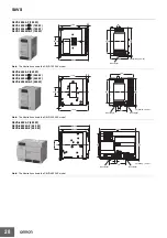
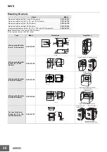


S8VS
Engineering Data
(60-W, 90-W, 120-W, 180-W, 240-W, and 480-W Models)
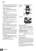
Derating Curve
Power Supply is used for applications with frequent inrush
current or overloading at the load end. Do not use the Power
Load (
%
)
−
20
−
10 0 10 20 30 40 50 60 70 80
120
100
80
60
40
20
0
1
See note 1.
Ambient temperature (°C)
Note: 1. Using side mounting bracket for right-side mounting
(excluding 240-W models). UL certification conditions do
not apply if the side mounting bracket is used.
2. Internal parts may occasionally deteriorate or be damaged.
Do not use the Power Supply in areas outside the derating
curve (i.e., the area shown by shading
A
in the above
graph).
3. If there is a derating problem, use forced air-cooling.
4. When using a 480-W model at an input voltage of 95 VAC
or less, derate the load by at least 80%.
5. DC Inputs for BE Models
If the input voltage is less than 100 VDC, reduce the load
given in the above derating curve by at least the following
factor.
60-W models: 0.9 max.
90-W models: 0.85 max.
120-W/180-W/240-W models: 0.8 max.
Supply for such applications.
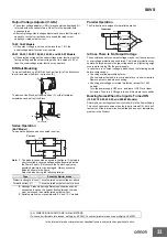
Peak Output Current (S8VS-48024
@
only)
The peak current must satisfy the following conditions.
Input voltage range: 200 to 240 VAC
Peak current value: 30 A max.
Peak current pulse width: 2 s max.
Cycle: 60 s min.
Note: 1. Two seconds after the peak current is reached, the peak
current limiting function operates to stop the peak current
flow.
2. It takes 60 seconds for the peak current to be able to flow
again.
3. The peak current limiting function prevents the peak current
from flowing at 100 to 120 VAC.
Peak current limit
2 s
60 s min.
Peak current
condition
Overcurrent
protectionpoint
Output current
0 A
Overvoltage Protection
Consider the possibility of an overvoltage and design the system so
that the load will not be subjected to an excessive voltage even if the
feedback circuit in the Power Supply fails. If an excessive voltage that
is approximately 130% of the rated voltage (but approximately 110%
of the rated voltage for the S8VS-09024
@@@
S) or more is output, the
output voltage is shut OFF. Reset the input power by turning it OFF
for at least three minutes and then turning it back ON again.
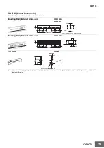
Mounting
O
u
tp
u
t
v
oltage (
V
)
Upper
Upper
Overvoltage protection
operating
+30%
Correct
Incorrect
(approx.)
+15%
Variable range
Rated output
voltage
Standard mounting
Face-up mounting
−
10%
Note: Improper mounting will interfere with heat dissipation and may
occasionally result in deterioration or damage of internal parts.
It may also result in failure of the maintenance forecast monitor
function. Use the standard mounting method only.
0 V
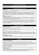
Overload Protection
The values shown in the above diagram is for reference only.
The Power Supply is provided with an overload protection function
Note: Do not turn ON the power again until the cause of the
that protects the power supply from possible damage by overcurrent.
overvoltage has been removed.
When the output current rises above 105% min. of the rated current,
the protection function is triggered, decreasing the output voltage.
Inrush Current, Startup Time, Output Hold Time
When the output current falls within the rated range, the overload
protection function is automatically cleared.
60-W/90-W Models
120-W/180-W/240-W/480-W Models
O
u
tp
u
t
v
oltage (
V
)
Intermittent operation
O
u
tp
u
t
v
oltage (
V
)
0
50
100
0
50
100
Output current (%)
Output current (%)
The values shown in the above diagrams are for reference only.
Note: 1. Internal parts may occasionally deteriorate or be damaged
if a short-circuited or overcurrent state continues during
operation.
2. Internal parts may possibly deteriorate or be damaged if the
24
AC input
voltage
AC input
current
Output
voltage
90%
96.5%
Startup time (1,000 ms max.)
Inrush current on input application
Input OFF
Input ON
Hold time
(20 ms min.)
Содержание S8VS 120-W
Страница 34: ...MEMO 34 ...


